
It recently came to my attention that cam sensors were in very short supply for the '96-06 Gen II and III Vipers. Chrysler discontinued them, then the aftermarket abandoned them too. There are a few new sensors on the market. If you absolutely need to have an original style sensor, contact Viper.Paul, he's our best(and seemingly only) resource for it. Me being me, decided I could come up with an alternative.
There's nothing special about a cam sensor. It's just a three wire(5V in, ground, signal) hall effect sensor. It works by sensing the magnetic difference between a raised ridge and a low area on the cam gear. Knowing that, I set out to find a replacement sensor. I figured if I couldn't find one that fit, I would just machine up an adapter.
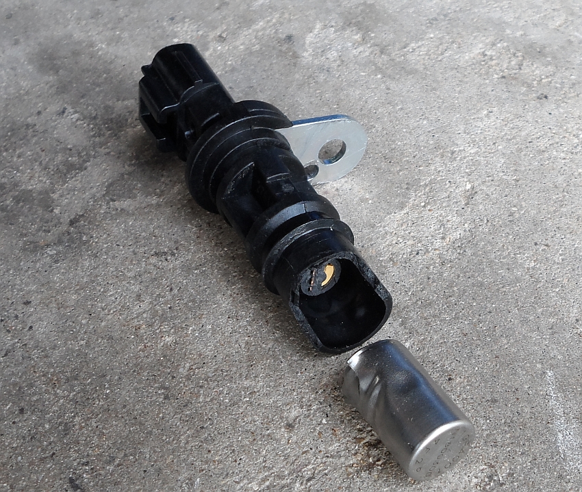
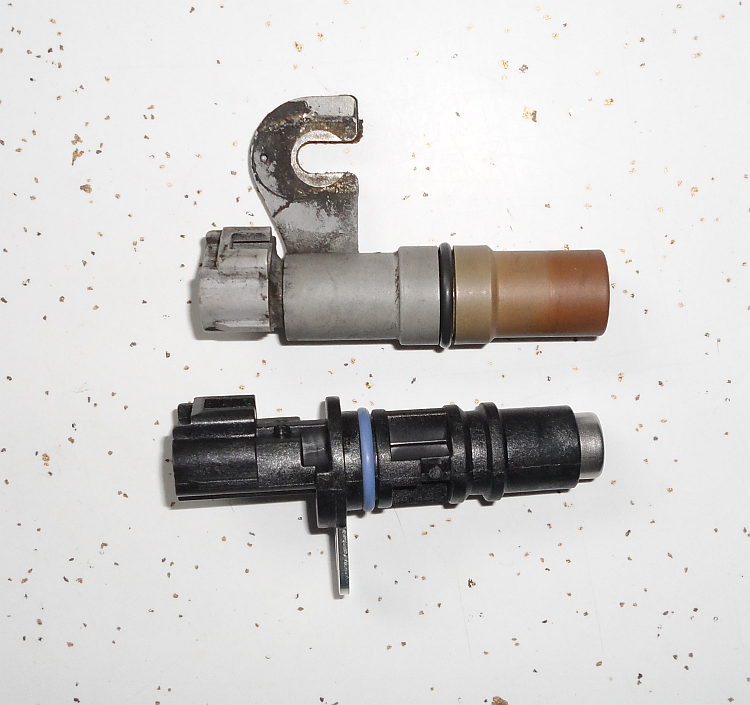
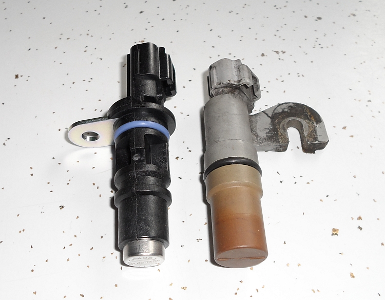
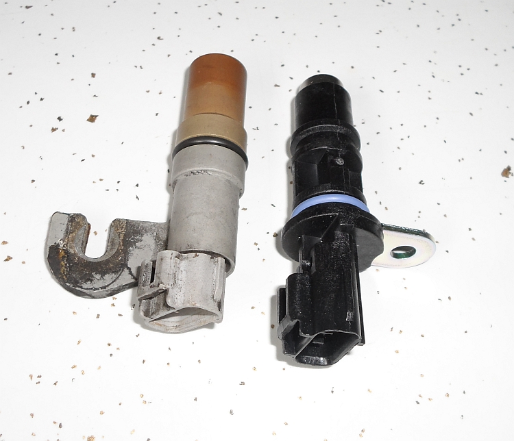
As luck would have it, there is an available sensor that fits the hole in the block. It's the sensor from 2000-2008 Dodge 3.7L, 4.7L, 5.7L, and 6.1L engines used in Rams, Dakotas, Durangos, and Chargers. It also fits a few Chryslers, and a ton of Jeeps. They used this sensor in hundreds of vehicles, and is is readily available through any parts store for around $25. The specific application I gave the counter jockey was a 2006 Dakota 4.7L. It's BWD part# CSS635. This sensor doesn't just fit the hole, it's exactly the same diameter as the original. Even the electrical plug is the same. The only problem with this sensor is that it's meant to attach differently, so the bracket is wrong. Here's my original Viper sensor(grey) next to the new Dakota sensor(black):
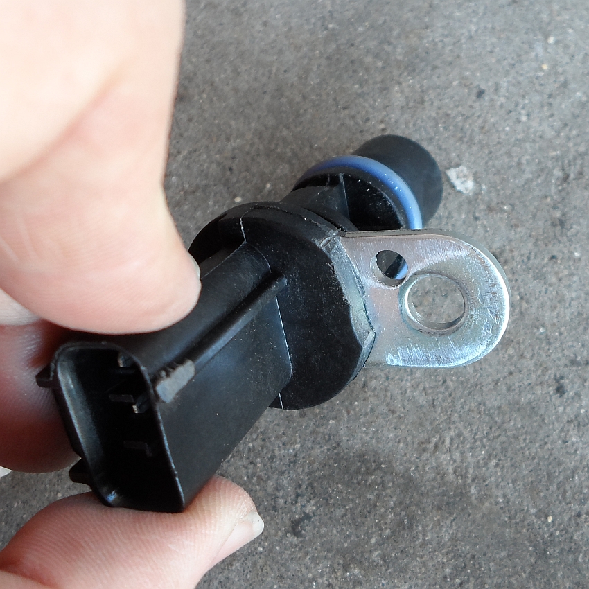
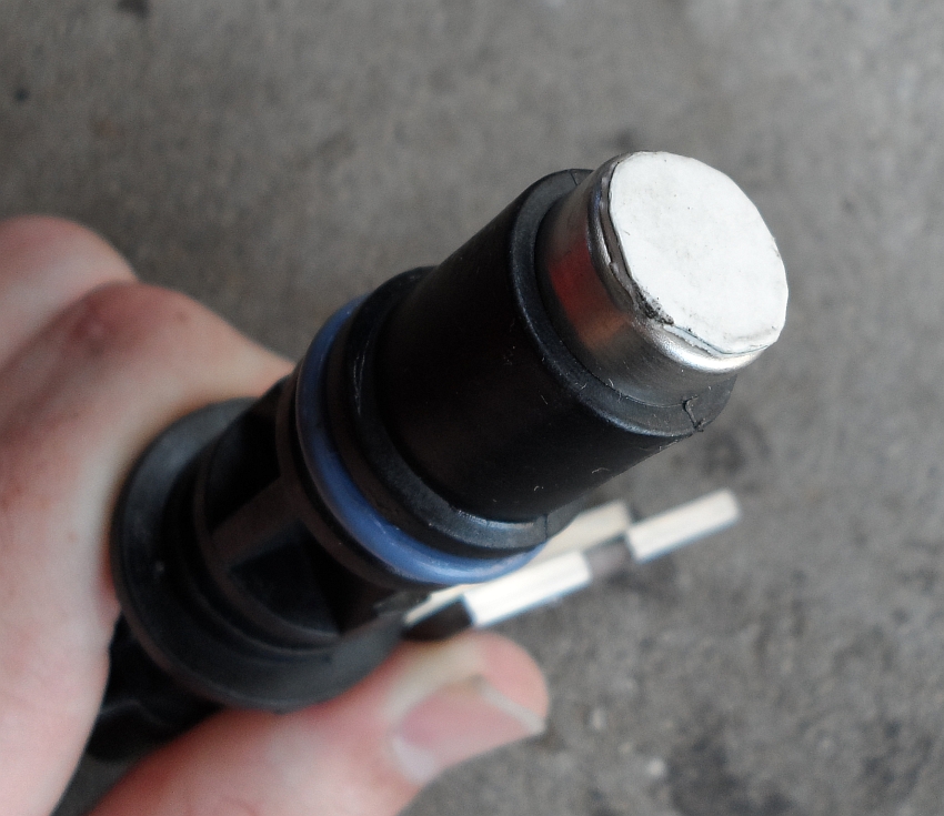
It looks quite a bit different, but dimensionally, it's actually very close to the original part. It's even already got a groove towards the front to move the o-ring into. This sensor is so close to the original that all we need is an adapter bracket to attach it to the Viper block. Unfortunately, the tab sticks out right where the bolt on the block goes. So, we can't use the hole already in the bracket, there's just not enough room for the hold down bolt. We need to get the sensor tab away from the Viper's mounting bolt, and give the sensor the depth adjustability of the original.
Here are the supplies you'll need to get. All are available from any hardware store.
3/4" x 3/4" x 1/8" aluminum angle
10-24 x 1" socket head cap screw
10-24 locknut
#10 x 1/4" spacer
one #10 washer
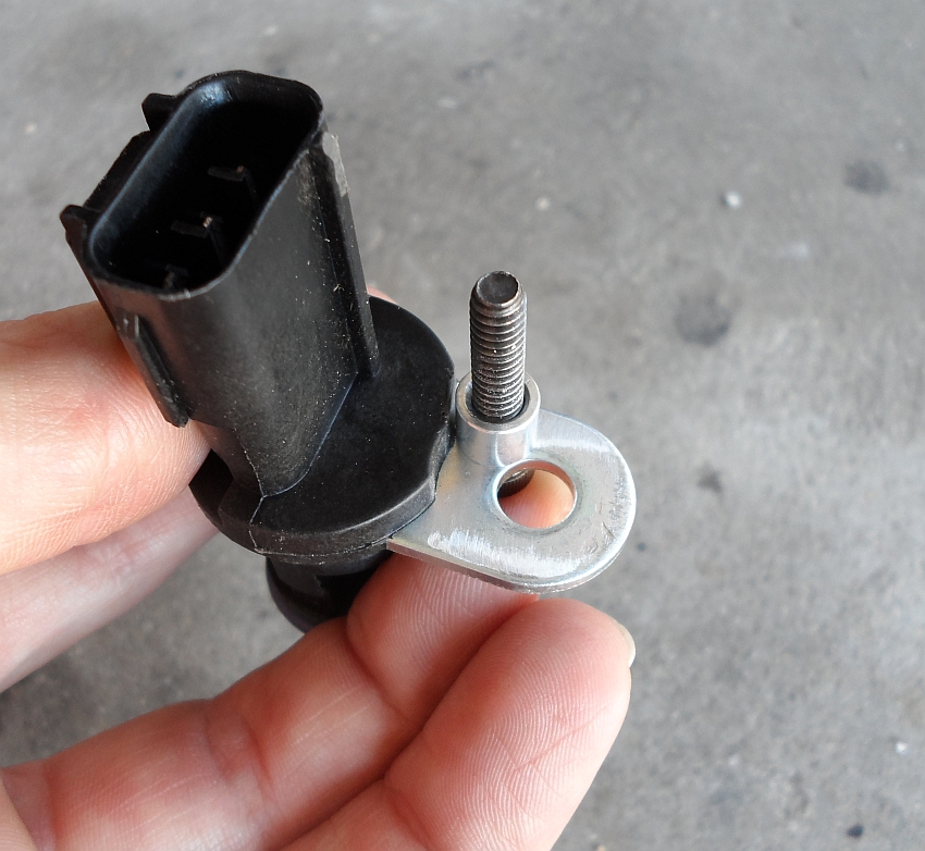
First, a hole needs to be drilled in the tab. I'm using a 10-24 allen screw and this is just a clearance hole, so the hole gets drilled with a #9 drill(13/64" is close enough if you don't have a number drill set). The location of the hole isn't critical, the bracket we're going to make has a bit of adjustment built into it.
Then, we need to do some slight clearancing of the plastic molded over the tab. A large flat file makes short work of it. What we need is just enough clearance for the spacer.
You don't need to file off much, just enough so that the spacer will sit flat on the tab:
One hole, and some filing. Other than moving the o-ring to the other groove, that's all the modification the sensor needs. If you choose, you can cut off the outer portion of the tab through the original bolt hole. It's not necessary, but will give you a little more access when it comes time to bolt it to the block. I chose not to.
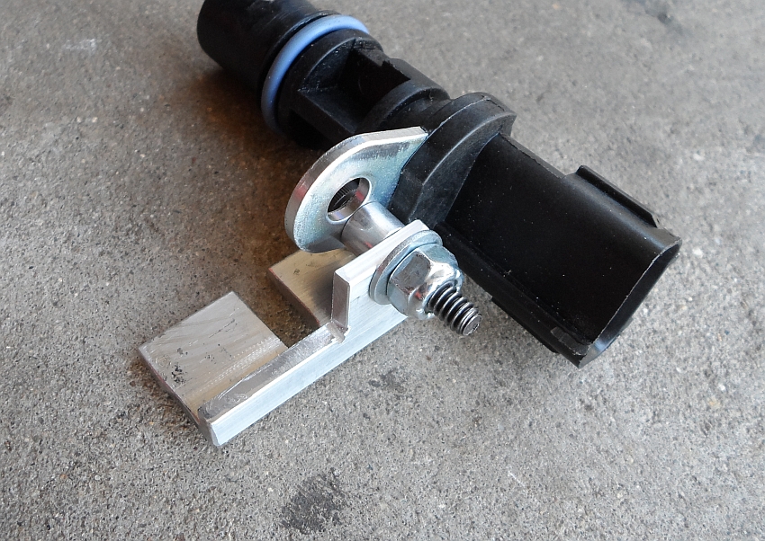
With the sensor modified, all we need is the bracket. I used 3/4" x 3/4" x 1/8" aluminum angle. The bracket is very simple, it's just a drilled hole and a cut slot. There is a little bit of fudging room, so if your dimensions don't exactly match mine, it should still work.
A hacksaw, cutoff wheel, or Dremel will work for cutting it out, and the same drill bit used to drill the sensor tab is used here. Here's how it attaches to the sensor. You don't want the bolt tight just yet, just a little snug. You want to be able to pivot the bracket a bit to get everything aligned. You can see here too where the o-ring gets moved to. This is my first "see if it will even work" bracket, so it's not overly pretty.
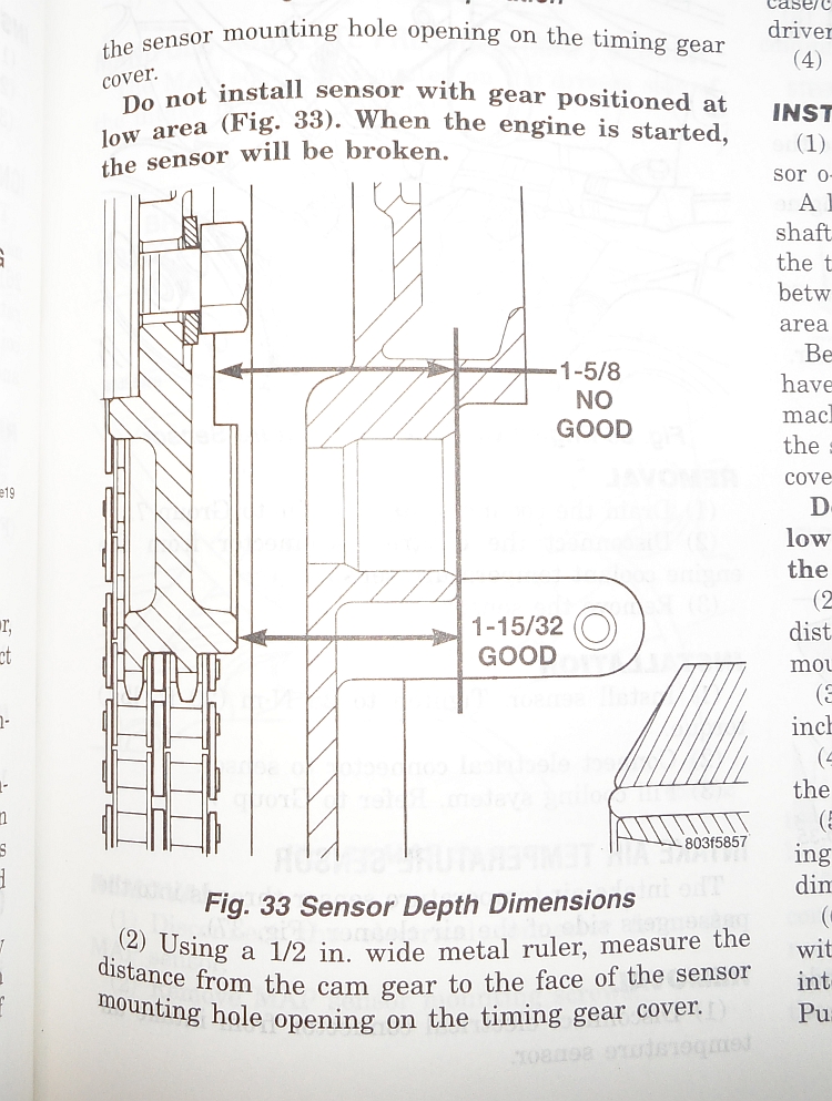
Now, before we go installing this thing, there's a very important step that can't be missed. Since the sensor is depth adjustable, we have to make sure the camshaft is positioned correctly. The pickup ring on the cam gear is basically a ring, half of it down low, half sticking up. If you don't have the cam in the right place and you're in the "low" portion of the gear when you set the sensor depth, the raised portion WILL break the sensor off as soon as you crank it over, and you WILL have to remove the oil pan to get all the pieces out(ask me how I know...).
To check where the cam is, you'll need a small ruler. A standard 6" machinists scale(available at most hardware stores) works great. You need to measure from the face of the block to the cam gear. I'll just steal a picture from my service manual for this one:
There's one last thing we have to do before installing this thing. As I mentioned, the Viper sensor is depth adjustable. Ideally, you want a .030" gap between the sensor and pickup ring. Too close and it could rub, too far and it won't pickup properly. Originally, there was a paper shim glued to the face of the sensor. It set the gap and got peeled off as soon as the engine was started. Since the Dakota sensor isn't supposed to be depth adjustable, it doesn't come with a shim. You can't buy a single shim(because who needs just one?) but a whole box of them is only $5 (Napa PN ECH CSS639, Standard PN PC339 crank and cam spacers are the same part). They're also available on e-bay. Since I have a digital caliper, cardboard, and spray glue, I made my own. Turns out that two layers of cereal box is exactly .030" and 3M 77 spray glue is sticky enough without being too sticky. Don't worry about the shim floating around in the oil pan. Because of the Viper's pickup arrangement and pan baffling, the disk can't get sucked into the oiling system, and should be flushed out at your next oil change.
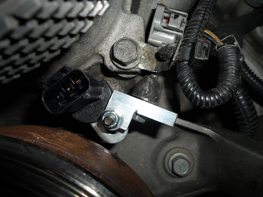
Now the fun part, actually installing the sensor. It's on the front left side of the block. I had mine in and out so many times I got pretty good at it. After removing the airbox and intake tubes, I found that it was actually easier to get to the sensor from the right(pass) side, reaching in under the oil cooler. Stubby wrenches are a big help. Lubing the o-ring with some oil helps too. The spacer shim will set the depth, you want just light pressure against the cam gear. Once you get the sensor in place, you can get the bracket lined up where it needs to be and tighten the bracket bolt and hold down bolt(it's not actually tight yet in this pic).
Plug the plug in, put the airbox back on, and that's it. If you've done everything right, your car should fire right up. If you hear a "crunch" as soon as you hit the key, you've probably broken the sensor off(oops...). I've currently got this setup running in my '97, and it's been working perfectly.
This will fit '96-'06 Gen II/III Vipers. It may also work on Gen Is, but I'm not sure. The Gen I sensor is slightly different, but I'm not sure what's different about it. I think it's just the plug, but I'm not sure. If it is just the plug, this will work on Gen Is too, just splice in the proper pigtail for the new sensor.
Results 1 to 25 of 33
-
07-26-2015 #1Enthusiast


- Join Date
- Oct 2013
- Location
- Wisconsin
- Posts
- 671
A $35 Gen II/III cam sensor alternative(and maybe Gen Is too)
Last edited by Bugman Jeff; 07-26-2015 at 02:13 PM.
-
07-26-2015 #2Enthusiast
- Join Date
- Dec 2013
- Posts
- 126
Bravo!
-
07-26-2015 #3Enthusiast
- Join Date
- Dec 2013
- Location
- Mass
- Posts
- 1,079
Your efforts / solution are appreciated!
-
07-26-2015 #4Enthusiast
- Join Date
- Oct 2013
- Location
- Ontario,MCVO,PA,OH
- Posts
- 2,671
Great info !
Thanks for Sharing !
-
07-26-2015 #5Enthusiast
- Join Date
- Nov 2013
- Posts
- 1,711
Wow! Great job! Someone should make this bracket and sell them. I'm going to buy up all these sensors and corner the market... lol
-
07-26-2015 #6Enthusiast
- Join Date
- Nov 2013
- Location
- Uniontown, OH
- Posts
- 93
Awesome work! Thanks!
-
07-26-2015 #7Enthusiast
- Join Date
- Feb 2014
- Posts
- 368
I love finding out about generic parts that work on the Viper. My asshole hurts every time I pay the Viper tax, and I need to ease the pain. Thanks for the write up
-
07-26-2015 #8Enthusiast
- Join Date
- Oct 2014
- Location
- Driving around with contaminated fluids braking at 95% while squirting WD40 in people's locks
- Posts
- 3,036
Great work by the OP for doing this. But compared to the cost of the OEM sensor which contrary to all these threads about unavailability is still available at uninflated prices, the bracket and sensor would have to be manufactured and sold at that same price range. Originally Posted by Sybil TF

Maybe you can get the hubby to make yours TF?
-
07-26-2015 #9Enthusiast
- Join Date
- Nov 2013
- Location
- Chandler, AZ
- Posts
- 2,463
Excellent job and a great DIY resource for the future possibility that the sensors go out of stock completely and don't get another run produced.
-
07-26-2015 #10Enthusiast
- Join Date
- Nov 2013
- Location
- WIsconsin
- Posts
- 687
Nice job thanks for the detailed info on this fix!
-
07-26-2015 #11Enthusiast
- Join Date
- Nov 2013
- Posts
- 1,711
Where other than Scharf that you mentioned? I have called 4 different places and none can get a new one. Yeah I think he could make one, getting him to is a different story lol Originally Posted by dave6666
-
07-26-2015 #12VOA Member
- Join Date
- Oct 2013
- Location
- Banned
- Posts
- 3,325
Well done Jeff! Thank you.
-
07-26-2015 #13Enthusiast
- Join Date
- Jan 2014
- Posts
- 235
Great work and thanks for sharing!
-
07-26-2015 #14Enthusiast
- Join Date
- Oct 2013
- Location
- New Braunfels, TX
- Posts
- 1,836
Congratulations on taking a logical approach to this situation and not throwing up your hands and screaming "the sky is falling" like so many others out there. Special accolades for a great writeup with detailed visuals that make it easy to follow!
-
07-26-2015 #15Enthusiast
- Join Date
- Oct 2014
- Location
- Driving around with contaminated fluids braking at 95% while squirting WD40 in people's locks
- Posts
- 3,036
lol fortunately the temporary insanity that caused the prices to elevate has passed and now you can get them for pre "the sky is falling" cost. Let alone the DIY method which is obviously cost effective. Originally Posted by GTS Dean
-
07-26-2015 #16Enthusiast
- Join Date
- Oct 2013
- Location
- North Carolina
- Posts
- 1,235
I'd think that would be the easy part... Originally Posted by Sybil TF
-
07-26-2015 #17Enthusiast
- Join Date
- Oct 2013
- Location
- Near PIttsburgh, PA
- Posts
- 353
Awesome job! Glad to see a solution to this problem. Thanks for taking the time to make and share it. At about how many miles are these going bad or is it just random?
-
07-26-2015 #18Enthusiast
- Join Date
- Oct 2013
- Location
- Millersville, PA
- Posts
- 577
Great! Thanks for sharing.
-
07-26-2015 #19Enthusiast
- Join Date
- Nov 2013
- Posts
- 1,711
Yeah right. Originally Posted by C.J
-
07-26-2015 #20Enthusiast
- Join Date
- Aug 2014
- Location
- Wappingers Falls, NY
- Posts
- 276
First, congrats for making it work. Second, thanks for spreading in the info.
-
07-26-2015 #21Enthusiast
- Join Date
- Oct 2013
- Location
- Wisconsin
- Posts
- 671
Thanks all. It's probably my imagination, but I swear my car runs smoother with the new sensor. The magnet in the new sensor is slightly stronger than the original, so if it's not my imagination, it could be the new sensor giving a more accurate signal. But it's probably just my imagination...
Looking at the pictures, it looks like the Gen I uses the same sensor, but with a different plug. If we can get confirmation of that, then just a new pigtail spliced into the wiring harness will allow this to work on Gen Is too.
I thought about drawing up a bracket incorporating the spacer that could be CNC'd so all you'd need is the bracket and a bolt(no washer, spacer, or locknut), but once you add in the labor and machine time to cut out a bracket like that, you're approaching the cost of an original style sensor. One of my goals, aside from having something a guy could put together at home, was to keep the cost as low as possible. With the sensor and all the materials, it's right around $35(the 3' strip of aluminum angle was $12 from the local hardware store). For what it's worth, the BWD sensor from Advance Auto is the exact same sensor as the one from Napa. Same mold marks, same stampings, everything.
I would also like to stress that I wasn't kidding about checking the block face to cam gear depth being the most important part. If you get it wrong, you WILL break a sensor. It's not just this particular conversion, but all depth adjustable sensors. If the cam gear is in the wrong place, you WILL break the sensor. If that happens, you'll have to drop the pan and fish out all the pieces. The pan comes off pretty easy, but it's a hassle to do.
It's a purely random thing. The sensor is just a magnet and some wires, there are no moving parts to wear, and no good reason for them to fail. They just sometimes do. Originally Posted by PittsburghRT
Last edited by Bugman Jeff; 07-26-2015 at 10:46 PM.
-
07-26-2015 #22Enthusiast
- Join Date
- Jul 2015
- Location
- Wesley Chapel, FL
- Posts
- 249
Thank you soooooooooooooo much Jeff..... This is awesome!!!!!!!!!!
-
07-28-2015 #23Enthusiast
- Join Date
- Oct 2013
- Location
- Wisconsin
- Posts
- 671
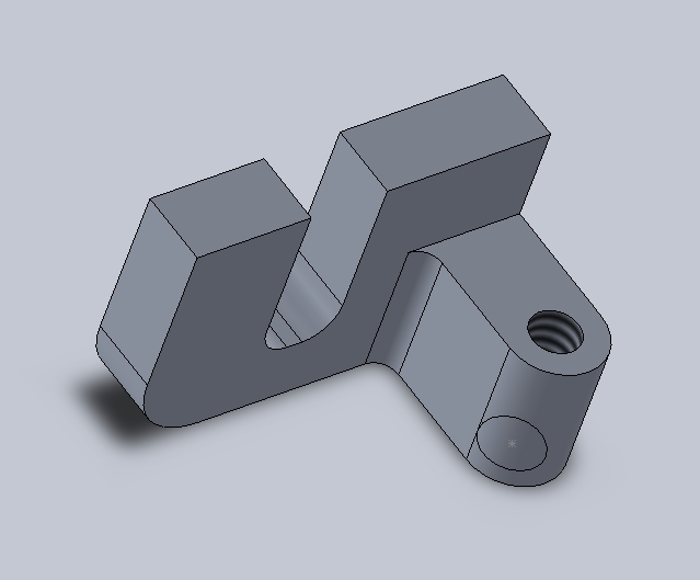
Just minor update: The whole point of making the bracket the way I did was so that a guy could make one for himself in his garage without special tools. Since there are people who have access to greater means, I decided to draw up a CNCable bracket. It's still dirt simple and can be machined entirely in one setup, except for the purely cosmetic radiused corner on the bottom left side. It eliminates the need for the spacer, washers, and locknut. If you have access to a CNC mill and want to make one, I can send you the Solidworks file.
Last edited by Bugman Jeff; 07-30-2015 at 12:42 PM.
-
07-28-2015 #24Enthusiast
- Join Date
- Oct 2013
- Location
- North Carolina
- Posts
- 1,235
Could it be that the original sensor wasn't set at a .030 gap? Originally Posted by Bugman Jeff
As always, your solution is well thought out and practical. Thank you very much for taking the time to share your solution.
-
07-29-2015 #25Enthusiast
- Join Date
- Sep 2014
- Posts
- 145
You sir are awesome.


 Reply With Quote

Bookmarks