


Big Brake Upgrade on my Gen 2 Viper
So I went ahead and did it. I upgraded the brakes on the Viper. I've seen some write-ups on this but I felt that there has not been one in a while and I wanted to add a bit more detail. I will give you a listing of all the parts (well... what I remember as I am writing this) and the tools I used.
This will be a long one with lots of photos and text. I will try to include it all. It may be overkill for some, but I rather provide as much detail as I can. If you know the info... skip forward. If you need detail... hopefully I give you all you need.
NOTE: This writeup is setup by sections. In other words, Rear modifications and installation, brake rebuild, front brakes, etc. It is not sequential. Just be aware that this is not a step by step in that sense. For example, I detail the rear first. In order to do that, I have to have removed the front calipers and rebuilt them in order to install them on the rear. However, I don't get to the removal of the fronts until later in the write up. Bottom line... you'll need to jump around a bit.
Also, I will not detail the left and right sides. Obviously, what you do on one side, you repeat on the other.
Plan:
Improve the braking of my Gen 2 to the sub-100 foot levels of the later Vipers. I own a 2002 Viper GTS Final Edition. To do it... I will upgrade the front and rear calipers and rotors.
Background from the research I did before I made the final decisions.
The stock brakes on the Gen 2 Vipers are:
- Front: Brembo manufactured four piston 42/38 calipers in front. This means that the pistons on the caliper are 42mm and 38mm, two of each. The rotors are 13 x 1.26 inch rotors.
- Rear: Single piston sliding calipers with a 42mm piston. The rear caliper also has the parking/emergency brake integrated. The rear rotors are 13 x .87 inch rotors.
2001 and 2002 ABS was standard. My car has ABS and this writeup assumes you have ABS. 1996 to 2000 were non-ABS car.
Braking Distance 60-0 is 115 to 117 feet
Stock Brakes on the Gen 3 and Gen 4 SRT-10 Vipers are:
- Front: Brembo manufactured four piston 44/40 calipers in front. The rotors are 14 x 1.26 inch rotors.
- Rear: Brembo manufactured four piston 42/38 calipers in the rear. The rear rotors are 14 x 1.26 inch rotors.
In addition to the basics listed above the master cylinder bore size on both the 2001-02 Vipers and the Gen3/4Vipers is 1.125". On the 2001-2002 Gen 2 Vipers, the stroke is 1.54". More on this later.
So based on this info, what I planned out was getting the calipers to match the setup on the Gen3/4 brakes. In order to do that, I need to upgrade the front calipers to 44/40 and the rears to four piston 42/38 calipers. The most cost effective way to do this is to get SRT-10 calipers for the front and transfer the Gen 2 front calipers to the rear axle. Not as difficult as you would think. The kit I used (relocation brackets) is from IPSCO which are excellent! The quality of the parts are outstanding. The fit is perfect and everything bolts up without issue as advertised. The parking brake is also awesome and the part quality is awesome. The engraved Sneaky Pete is gorgeous. Overall I would recommend the stuff blindly.
Parts List:
Gen 3 Front Calipers Part Numbers: 05136153AA and 05136152AA for the Left and Right
Gen 2 Front Calipers These are the ones on the car that I transferred back
Gen 3 DODGE VIPER StopTech Slotted Brake Rotors Part Number: 126-63055SR & 126-63055SL for the left and right (will be the new front rotors)
Gen 2 DODGE VIPER StopTech Slotted Brake Rotors Part Number: 126-63036SR & 126-63036SL for the left and right (will be the new rear rotors)
SRT10 Caliper Mount Kit - Front for GEN 2 Vipers (96-02) Part Number: IPS301
Gen 2 Caliper Mount Kit - Rear using 13" Gen 2 front rotors Part Number: IPS304
Gen 2 1996-2002 Stainless Steel Braided Flex Brake line kit Part Number: IPS186FR (Both Front and Rear)
Viper 3/8" Thick Hub Centric Wheel Spacer Part Number: IPS111-38 (4 units)
Extended Lug Nuts to use with Spacer Plates Part Number: IPS189 (4 sets of 6 needed)
Hawk Performance HPS Brake Pads - Viper Gen 3 Front Part Number: HB193F.670
Hawk Performance HPS Brake Pads - Viper Gen 2 Front Part Number: HB194F.665
Viper Mechanical Parking Brake Kit for 13 inch rotors Part Number: IPS090-13
Got mine with Sneaky Pete for the Gen 2
A note on the above calipers. I purchased a set of used calipers from X2Builders. I've purchased a number of parts from them before and have had nothing but great parts. I have replaced a broken e-brake handle and a replacement tank and replacement cover panel. (you can search up my fuel tank replacement) However, since the brakes are critical, I purchased rebuild kits for all the calipers including the ones on the car. I rebuilt all four calipers. To do that I used:
Centric Brembo Rebuild Kit for Gen 3/4 Front Calipers Part Number: 143.03005 One Per Caliper
Centric Brembo Rebuild Kit for Gen 2 Front Calipers Part Number: 143.63023 One Per Caliper
The centric parts are great (Centric is the parent company for StopTech) and each kit replaces all the seals and dust boots.
In addition to the rebuild kits I replaced the bleeder valves for the brake calipers. As FYI for you, you need to get those in a a M10x1 thread by 29mm length. The length from the bottom threads to the point of the bleeder is 6mm. I found the eight (two per caliper) at NAPA Auto Parts locally.
In terms of tools, you'll need / I used:
Reciprocating Saw and/or Cut-Off Wheel on a grinder or angle grinder.
Grinding disk on an angle grinder
Sanding Discs / Poly cookies
Large Channel Locks
Torque Wrench that will provide up to 110 ft/lbs of torque.
Allen sockets for the bolts used to attach the new brackets and calipers. You will need a 10mm allen and an 8mm allen key to fit the socket. Remember to get any adapters you may need to attach these to the torque wrench.
Of course.... Set of short and long metric sockets. Largest socket you'll need is an 18mm if memory serves. A few open end wrenches. You'll need these especially for the brake lines and bleeders. Shorty wrenches help but not needed.
Last thing... get four large plastic boxes / trays. You'll spend $20 but you place one under each wheel when you start pulling calipers and lines off, you can let the fluid drain into the trays.
Results 1 to 25 of 67
Hybrid View
-
05-15-2014 #1VOA Mamba Member

since 2013
South Florida

- Join Date
- Nov 2013
- Location
- Miami, Florida
- Posts
- 600
Viper Big Brake Upgrade - Gen 2 Viper
Last edited by Luisv; 05-21-2014 at 02:30 PM.
Luis V.
Miami, Florida
2002 Dodge Viper GTS - FE #298 & 2013 Dodge Viper GTS
-
05-15-2014 #2VOA Mamba Member
since 2013
South Florida
- Join Date
- Nov 2013
- Location
- Miami, Florida
- Posts
- 600
Rear Section
OK so to the process... I started with the rears. There is far more to do there so I figured I'd get those ready first. On the rears, the stock calipers are single piston with the integrated parking brake. Since the front calipers (Brembos) don't have the parking brake integrated we need to add the mechanical brake. The rears then basically require two things: Installation of the parking brake and the installation of the bracket for the new calipers. To install the latter requires the dreaded cutting of the rear bearing carrier.
The stock setup of the Gen 2 Rear Brakes.

Below is the back side. Here you can see the two caliper mounting bolts, the stock brake lines, the spring for the parking brake mechanism and the parking brake cable at the very top.

To remove the caliper you need to disengage the parking brake cable. This is simple. First, separate the ABS cable (soft/flexible black cable attached with a few clips to the parking brake cable). Be careful not to pull on the ABS cable too much or where it connects. You don't wnat to damage these.

Once you have done that all you need to do is compress the caliper with the channel locks and pull the cable. Don't go nuts with the pliers, compress enough to get the cable free.

The released cable.

Once that is done, then just two bolts gets the rear caliper off. Don't remove the brake line until you need to so that you don't have to worry about brake fluid. You'll get enough of that later. No need to open those lines until you need to. Below is the hub carrier with the caliper removed. To keep the lines from bursting... just hang the caliper on the suspension someplace. I used a couple of tie wraps and hung it off the upper arm.

Repeat for the other side and get the caliper on the other side off and out of the way.
The last thing you need to do here is remove the two bolts that hold the hub assembly to the aluminum hub carrier / knuckle. Remove just the two bolts that are on the same side as the caliper is mounted. It is important that you only remove those two so the hub does not move at all. You will put these back when you mount the bracket later on. You will replace them with the longer bolts included in the kit.
Now we move to the modification of the rear hub to accomodate the new bracket. To do this we need to cut away the "ears" or tabs that held the original caliper. I took my time here as I wanted an install that looked as clean and stock as I could get. In the other writeups I have seen most tell you to just get a saws-all/reciprocating saw to cut the ears off. Sounds easy enough but in reality to get a good clean look takes time and some care.
Since the hub/bearing carrier is cast aluminum, it is not hard to cut. To get the finished look I wanted, I decided to cut the tabs leaving some extra material there so I can grind down to where I needed them. Measuring and test fitting the new bracket as I went. So to cut the tabs I taped off the rough line I wanted to follow. This is pretty much as close as you can get with the reciprocating saw without having to deal with the hub and lug studs. You'll find that the saw (at least mine) hits the hub when cutting. You would need a very long blade to avoid it all together and I am not a fan of making metal cuts from 5 inches out with a 9 inch blade. I simply cut to leave the central portion of the tabs at the casting.
Below is the taped off guide and then the tabs cut off. On the second photo, notice the central portion of the area. You'll see where the casting is still visible. I do this to leave myself a guide when grinding down.

Here the cuts are made. It takes less than 10 minutes to make the cuts with the saw. Not difficult at all. The only thing I recommend is to oil the blade with a few drops of oil so as to avoid binding on the sides as you get deeper into the cuts. 3-in-1 oil works just fine.

 Luis V.
Miami, Florida
2002 Dodge Viper GTS - FE #298 & 2013 Dodge Viper GTS
-
05-15-2014 #3VOA Mamba Member
since 2013
South Florida
- Join Date
- Nov 2013
- Location
- Miami, Florida
- Posts
- 600
Here I hit the cuts with the angle grinder with a 36 grit flap disc installed. It makes real quick work of the remaining material on the tabs. In the photo below you see what I mean about using the central portion as a depth guide. I ground the rough cut tabs down until that central area (where I am pointing) is gone. Very important to be as even as possible. You want the final edge to be parrallel to the hub cariier. Take you time and check the area with the bracket or straight edge to make sure it is even.

I used the bracket as a reference for the line. Notice how the aluminum hub carrier touches the bracket unevenly? Specifically the center still shows a gap and the bottom edge shows one as well. Grind down and CHECK FREQUENTLY. This is aluminum and grinds down pretty easily. You don't want to take off too much material.

Here I am getting close to the end. The edge is far straighter than before and the gap is being formed. The bracket is placed there now with the bolts finger tight so I know where it will sit.

As we grind down and get that edge straight I start to measure for a gap. What you are looking for is a gap of .030 to .050 inches. I took a feeler guage and checked for that gap. I used the .032 blade and made sure it fit easily all the way up and down. (the photo below is from the driver's side)

Once the the edge is done and you are happy with it, you want to grind down a casting mark on the back side of the carrier. In my case, it really did not get in the way, but I ground it down anyway. Below is the mark (between the bolt holes in the photo) that you want to grind smooth.

Once the back casting mark is gone and the edge finished, this is what it looked like. The gap is almost perfectly even and the gap is a minimum of .030 all the way from the top to bottom. One thing I did to keep this looking as "original" as possible is that after I got the edge smooth and straight I rounded the corners of the aluminum carrier/hub where the cuts were made. You can see that here in the photo if you look at the top an bottom corners where I cut. The other thing I did was polished the edge a bit with some poly cookies just to get rid of the scores left from the grinding. Stupid... nobody will ever see it... yes... yes... but I know it's there and I am stupid that way... ;-)

So to summarize this... I cut the ears off rough with the reciprocating saw using a metal cutting blade. Remember to oil it a bit to avoid binding. Then I ground down the left over tabs so as to get a straight edge. That was done with an electric angle grinder and a 36 grit flap disc. Once that was stright, using the bracket, I perfected the edge and got it so that the edge left a gap of .030" with the new bracket. The last part was done with an air angle grinder and 40 grit discs. I rounded the corners to make it look like the part was originally cast like this and then fisnished off the edge polishing it a bit with medium and fine poly discs. In all I spent about 45 miuntes to an hour per hub to get it done.
Once the cuts are perfect I mounted the brackets. I used the 12mm bolts provided with the kit. All you need to do is put some red Loctite on there and torque them down to 110 ft/lbs of torque.
This is the bracket viewed from above with everything torqued down.
 Luis V.
Miami, Florida
2002 Dodge Viper GTS - FE #298 & 2013 Dodge Viper GTS
-
05-15-2014 #4VOA Mamba Member
since 2013
South Florida
- Join Date
- Nov 2013
- Location
- Miami, Florida
- Posts
- 600
Continuing the rear...
From here on out, the rest is pretty much a bolt on process. The worst of it is done.
Now that the rear caliper brackets are both in place, I need to mount the parking brakes. To me, these look awesome. It's just a real good looking piece of gear. To get them installed it is pretty easy.
First CAREFULLY remove the bolts on the opposite side on the hub assembly. In other words the two bolts holding the hub on the knuckle on the side opposite the caliper bracket you just installed. Since the bracket is tightened down, you can remove these two without fear of the hub shifting at all. What you have to be careful of is the ABS cable. On the rear, the ABS cable runs up from behind, attached to the parking brake cable. Up above we separated the ABS cable from the parking brake cable when we disengaged it from the caliper.
The ABS cable attaches to the hub rotation sensor at the rear side of the hub. As you remove the bolts holding the hub on the knuckle you have a chance at pinching the cable. Just be careful with it.
Once the two bolts are off you have to remove the parking brake caliper from the braket (the kit is shipped assembled). Below is the shot of the kit again and the bracket separate.

Below is the bracket separated from the caliper. They are labled right and left. In the second shot notice the slot/cutout in the center. This is where the ABS cable will run.


To install the bracket just carefully place the bracket in place being certain that the ABS cable runs in the cutout. The kit comes with the longer bolts to accomodate the bracket and these get the red Loctite and are torqued to 110 ft/lbs as well.

The installed bracket from the front.

 Luis V.
Miami, Florida
2002 Dodge Viper GTS - FE #298 & 2013 Dodge Viper GTS
-
05-15-2014 #5VOA Mamba Member
since 2013
South Florida
- Join Date
- Nov 2013
- Location
- Miami, Florida
- Posts
- 600
Now that both brackets are in place we need to place the rotor on the rear hub. These rotors are the most apparent difference. The rotors are both 13" rotors but the differences are the width of the braking surface and the thickness of the rotor itself. The new rotors are 1.26" in thickness and the originals are .87" in thickness. Basically, they will give us more bite.
Check out the two rear rotors side by side. I then give you a close shot of the surface area so you see the differences.


Also, I wanted to note here that I went with the slotted rotors. I did this becuase slotted rotors improve braking in a number of ways. The first is the cleaning effect. They give the dust and water (if in wet conditions) a way to be removed. The slots also provides a way for pads to vent gasses in high heat conditions. Lastly, and the most apparent benefit is the cooling effects of the slots. The brakes cool better and reduce the potential for fade. Why I did not go with cross drilled brakes is becuase of the small risk of rotor cracks. There have been some that have complained about this in extreme conditions. I will not likely ever get to that point, but I'd simply prefer to avoide the chance.
OK so getting back to the installation of the parking brake caliper. You place the rotor on the hub and hold it tightly in place with a couple of lug nuts.
Tip: The rotors are side specific. In other words, there is a right and a left. The reason for this is the rotation of the rotors. Specifically the direction the cooling vanes INSIDE the rotor spin. They are designed and laid out such that the cooling effect is maximized with the rotor spinning in a given direction. The outer grooves are not the issue. When I first positioned them, I did it based on the slot direction. This is not correct and I caught myself before I finished up. If you notice in some of the shots of the rear step by step, you'll see I have the "L" rotor on the passenger side. Point is... they are labled and make sure you get them in the correct position.
Tip: while you are there... clean the lug studs. I pulled out the high speed rotary tool (Dremmel) with a small wire brush. I hit all the lug studs with it to clean off all the rust. Then to avoid the issue again, put a small amount of anti-seize on the lugs before you put the wheels back on. This will make these come on and off real easily.
Note on the photo below: This is a shot to display the way I held the rotor in place. You'll see that the rotor is already bedded. This shot was taken after I was done. You'll see that the parking brake and caliper are hanging there. Again... just to show you the way the rotor wa placed.

Once the rotor is on, you will install a set of spacers on the bracket. And then the caliper goes on after that. To make it easier I placed the bolts in far enough to hold the spacers in place.

The calipers then go in. There is an adjustment nut on the back of the caliper. (you can see it in the photo below) Tightening or loosening the bolts shifts the caliper in and out. You may have to adjust that slightly to get the caliper to slide in easily. Once on this is the caliper mounted.
The adjustment nut is the middle nylon lock nut along the top edge of the caliper.

Once the caliper is in place you need to adjust the position of the whole caliper (in and out in reference to the rotor plane) so that the clearance is between .005 and .010 inches on the inside of the caliper. In other words so the insdide parking brake pad is off the rotor by .005 to .010 inches. The distance between the pads is fixed so if you set the inside pad clearance the outside pad will likely fall into the gap needed. Here is how I did it...


Once the caliper is in place and the gap is set, you need to attach the parking brake cable. To do this you need to route the cable differently. You need to remove the clip holding the parking brake and ABS cable to the frame. Once that is done, you separate the ABS cable from the parking cable. Once separated, you can run the parking cable arong the front side of the suspension. Below is a shot of the routing of the parking brake cable.

To set the cable in place use a set of pliers to pull the parking brake cable out as far as possible. You can then hold it with a set of vise grips or locking pliers. Once you have that you can set the cable in place by compressing the parking brake lever a bit by hand.

- - - Updated - - -
To finish off the parking brake here are a few final shots.
This is the parking cable after routing it in front (refering to the car) of the suspension arms.

Other side.

This is the parking brake caliper in place with the cable run and attached.
Note on this photo: Again, this is a photo after everything was done. Take it as a reference

This shot shows you the ABS cable. You run this along the rear toe link on the rear suspension. I tie wrapped the cable where the ABS cable had the rubber grommets. Those grommets where used to hold the cable to the parking brake cable. Now you can use it to tie wrap the ABS cable to the link.

Now that we are here, I'd fix the parking brake cable to the upper suspension arm. You want to keep it ralatively low and close to the grease fitting on the upper arm. You also need to keep it close to the arm itself. This is because you are going to put a 12" wide wheel back on there. You need to make sure the wheel clears the cables and lines.

Now that the parking brake and four piston caliper bracket are installed, it's time to move onto the installation of the caliper itself.Luis V.
Miami, Florida
2002 Dodge Viper GTS - FE #298 & 2013 Dodge Viper GTS
-
05-15-2014 #6VOA Mamba Member
since 2013
South Florida
- Join Date
- Nov 2013
- Location
- Miami, Florida
- Posts
- 600
Rebuilding the Calipers
As mentioned in the beginning, I am using the front calipers from my car on the rears. Since these are 12 years old now, I figured I would rebuild them. Also, since I am rebuilding the SRT-10 calipers I got for the job, I figured rebuilding all of them would be smart. Doing this is a lot easier than you would think.
Here we grab the rebuild kits listed above. Each kit consists of four piston seals and four dust boots. Two are smaller and two are larger (42mm and 38mm in the case of the calipers I had on the GTS). The sizes are easy to realize when you pull them out of the pack.
I'll give you the basics here. There are plenty of other sources (YouTube has a few) that detail the rebuild.
To start you will have to pull the pistons out of the caliper. This is the hardest part of the rebuild. The trick is to be patient and go slowly. To have them protrude far enough to be able to pull them out you simply use compressed air blown into the brake line. AGAIN, GO SLOW, DON'T BLAST 90 PSI IN THERE. To avoid any one piston from just balsting out, use something placed between them to control how far they come out. I used the old brake pads. Fill in the space and simply blow the air in slowly.

As you get the air in there the pistons will come out. You may need to use wide welder's pliers or C Clamps (Be sure to protect the finish on the calipers) to control one or the other side. You may have to position spacers so as to hold two or three pistons in a given position to move the fourth out. Bottom line... go slow. Take your time and you will get them to move out a bit at a time. Get the pistons out partially and then you will remove the dust boots. Use a small jewler's flathead and pry out the seals from the center (between the pistons). There is a small cutout visible there. It will allow you to put the flathead in. Pry them up and remove all four from the the caliper seat. In the photo below I am removing one seal/boot and the other is already out.

seals out and off the pistons. To get them off the pistons, just pull them off gently. There is no need to pry here just stretch them off a bit.

Pull the pistons out by hand. If it's too tight, just blow air into the caliper to push them out. If one pops out, you will not be able to use air anymore. If that happens, put it back a bit tight against the seal (you'll feel it) and figure a way to hold it there. A bit more air slowly and the other pistons will move out. Again. Be patient and use the noggin.
Once all the pistons are out, you need to remove the old seals. Those are about 1/3 of the way in and in a groove cut into the wall of the piston openings of the caliper. You get them out, the easy way is to use a small pick. It's not hard... be carful not to mar the groove.

Now clean the caliper well. Use a brake cleaner and make sure the piston openings are clean. Make sure the seal groove in the piston opennings are clean along with the groove on the outside edge where the dust seals came out of. Once the caliper is clean wipe them down with a damp (not dripping) cloth to remove the residual brake cleaner. The caliper finish can get a cloudy film on it. This will resolve that. Dry them well. The brake cleaner is not likely going to damage the finish, but don't just spray everything and let it sit there. Better safe than sorry. Now clean the pistons well and inspect them. Make sure the sides are very smooth and have no gouges in them. Once everything is clean, you will install the new seals. Below are the seals, again the sizes are obvious and you will know where to put them in.

To install them, dip the seals in some brake fluid. This will lubricate the seal and allows you to install them easily. Make sure the seat well. Once those are in make sure everything is still clean.
Now move on to the pistons. You need to place the dust seals/boots on. The inside bevel edge of the boot goes towards the closed end of the piston. Below is how it should look.

Once you have the seals in place simply put the pistons back into the caliper. You will be able to do it with just your hand pressure. The trick is to make sure they go in evenly meaning that they are not going in at an angle. The whole thing is getting it over the seal. Once you pass the seal, the piston will slide in easily. Make sure the piston is clean and make sure there is a small amount of fluid in the piston opening on the seal itself. Don't put too much in there as that can make it harder to push it in. Just enough to moisten the seal. Once the piston is all the way down, make sure the dust seal sits all the way down.
I did all four calipers at this point. Now I am ready to start installing everything. The front calipers where powder coated black to match the factory fronts I have which on a 2002 are black. I prefered black... two reasons. First, it's a nice contrast against the red car and polished wheels. Second, brake dust and road dirt from driving is FAR less noticeable between the washes. Below is a shot of the calipers.
 Luis V.
Miami, Florida
2002 Dodge Viper GTS - FE #298 & 2013 Dodge Viper GTS
-
05-15-2014 #7VOA Mamba Member
since 2013
South Florida
- Join Date
- Nov 2013
- Location
- Miami, Florida
- Posts
- 600
.
.
Finishing the Rear
OK... so we have the rear parking brake in place. Time to start placing the rear calipers in place. The front calipers, now rebuilt, will move to the back. However, to orient the calipers correctly, you will swap sides. The calipers should be set in place with the bleeder screws pointing upwards. For that to happen, the front passenger side caliper will move to the driver side rear and the front driver caliper will move to the rear passenger side.
The caliper is held in place with two 12mm bolts. I placed the caliper in place with the bolts hand tight. I then attach the steel brake line with the banjo fitting onto the caliper loosely. The other end goes to the new brake line fitting installed on the frame. These came with the line kit.
This is the caliper in place with the brake line in place.

The brake line routing going to the new frame fitting installed.

The frame fitting is easily installed. You have to remove the old fitting which is part of the brake line assembly. To remove it you use an open ended wrench and slowly loosen the rigid brake line at the old fitting. When you remove the rigid line from the old fitting, you remove the frame mounting bolt and the line will come off. Place the new frame fitting in place. These are position (corner by corner) specific. To see which one goes where, simply get the new fitting bracket shape to match the one on the line you are pulling off. It's obvious so no worries. Now I placed the frame bolt in loosely to allow a bit of play. With that you can wiggle a bit to set the rigid line fitting/nut in place. Then push the rigid line in such that you see and feel it bottom out in the new fitting. Then thread the nut on by hand to avoid cross threading it. Once there I move the rigid line in and out to make certain it is not bending and that the tightening will not break it. From there tighten the fitting with the wrench. Tighten the frame mounting bolt last. Once that is all down, attach the steel line to the fitting. Below is a close up shot of the brake line frame fitting with the brake line attached.

a close shot of the rear fitting.

Tighten the line up keeping the orientation and bend more or less as you see it in the photos. Basically, the banjo fitting points up and the curve in the line is up towards the upper suspension arm.
The caliper is tightened to the bracket with the 12mm bolts at 85 ft/lbs of torque. Below is everything all installed. (if you read above about the rotor orientation... this one is correct)

At this point tie wrap the lines and parking brake into their locations. Remember to leave play in there. These lines & cables must allow for the suspension travel.

Luis V.
Miami, Florida
2002 Dodge Viper GTS - FE #298 & 2013 Dodge Viper GTS
-
05-15-2014 #8VOA Mamba Member
since 2013
South Florida
- Join Date
- Nov 2013
- Location
- Miami, Florida
- Posts
- 600
.
.
.
FRONT
So now we move forward. This is not in sequence... obviously, I had to have removed the front calipers by this point in order to have them for the rear. However, for the sake of clarity and to finish the writeup in sections, I'll detail the removal of the fronts here.
The stock front setup before I take it apart.

The back side of the stock setup. To remove this claiper is straight forward. First thing you need to do is remove the ABS line from the bracket in the photo. The bracket is part of the brake line and holds the ABS line via a rubber grommet. Gently grab the grommet (or as close to it as you can) and wiggle the wires up and out. Next remove the bracket on the line . The bolt you need to remove is the lower hub bolt holding the bracket as well. While there remove the upper hub bolt as well since you will need to anyway to install the new bracket. I did not remove the brake line at the caliper. Instead, I removed the line at the frame fitting. To get the caliper off remove the two 12mm bolts just above and below the brake line fitting in the center. You will have to compress the pads in a bit. Just pry them from the rotor (you are replacing it anyway) with a flat head. You don't need to come off much. Be careful not to mar the caliper.

This is where I removed the brake line. I am pointing to the frame fitting (part of the brake line). This will be replaced by the new frame fitting on the kit. As with the rear, compare the parts and pick the one who's bracket is the same shape.

As with the rear, carefully remove the rigid brake line from the fitting. The position of the fitting is a bit of a pain. You will need to remove the rigid line first before you can get to the bolt mounting it to the frame. This is time consuming because you dont have a great deal of room and you will have to turn the wrench a great deal. Even with shorty wrenches, I was only able to muster 1/4 turn at a time of the brake line fitting nut. Take your time, no ruch, remove it and be careful not to bend the line as you hold it out of the way and or damage the threads on the nut. Once the line is off, remove the frame mounting bolt.
To install the new fitting, reverse the process. Here you will mount the bracket first. Leave it a little loose. In other words, leave it such that you will need only a turn or two to tighten. The wiggle is more than enough. Then push the rigid line in such that you see and feel it bottom out in the new fitting. Then thread the nut on by hand to avoid cross threading it. Once there I move the rigid line in and out to make certain it is not bending and that the tightening will not break it. Once you are happy, tighten the line nut. Finally, tighten the frame bolt with an open end wrench.
This is what you'll have

from below

Now we need to mount the bracket. This is simple. The front bracket is held in place with four bolts. Two go into the tabs where the calipers were held and the other two are where the hub bolts go. You will have all four bolts for these. Here the brackets have a small indentation to accomodate the casting marks. No need to remove those. Place the bracket in place and put the bolts on. Do not tighten just yet as we need to put a bracket back in....
Below is the shot with the bracket in place from behind and from the front side.


- - - Updated - - -
Now we move onto what I did to accomodate the ABS wires. The ABS wires were attached to the brake line bracket. Since I am replacing those, I will lose the bracket and subsequently the support of the wires. I did not like that idea. What I did was modify the bracket I had.
Below is the brake line once removed from the caliper

What I did was cut the bracket off the line. I made the cut as close to the line as possible to keep the c-socket used for the ABS wires. I then rounded the corners of the bracket and cleaned up the edges to make them nice and smooth. For good measure, I polished it off with some poly cookies. (Again... yes... a waste of time... but I like things clean) The resulting piece is below.

Once that was done I placed the bracet back in place and used the hub bolts to attach it as it was there before. To accomodate the extra distance out it rides off the hub (the caliper bracket) I simply bent up the bracket so as to keep the ABS cable along a similar path. Put red Loctite on the four bolts. The two 12mm bolts (with the 10mm allen sockets) are tightend to 85 ft/lbs of torque. The two 10mm bolts (8mm allen socket) holding the hub and ABS bracket are tightened to 45 ft/lbs of torque. Below is the bracket all done.

Once this is done we mount the rotor and hold it in place with a pair of lugs. Make sure you get the orientation correct. Below are the old and new front rotors. The difference here is that the new fronts are 14" rotors vs. 13". Both are the same 1.26" thickness.

The braking surface closeup.

After that, get the caliper on the bracket. The SRT-10 Calipers are radial mounted. Place some red Loctite on the 12mm bolts (these are long) and tighten them down to 85 ft/labs as well. Below is everything mounted up. Remember, bleeder screws up. There is a right and left caliper.
From the edge.

Check that everything clears well. The caliper does not hit the rotor ect.
Once you are good, as with the rear, put on the steel brake line. The banjo fitting goes pointing up and the line will ultimately run up and over by the upper suspension arm. Below is the shot of the line coming off the frame fitting.
 Luis V.
Miami, Florida
2002 Dodge Viper GTS - FE #298 & 2013 Dodge Viper GTS
-
05-15-2014 #9VOA Mamba Member
since 2013
South Florida
- Join Date
- Nov 2013
- Location
- Miami, Florida
- Posts
- 600
.
.
Brake Pads
We're getting there... Now we need to finish up. Time for brake pads. If nothing else, this is the best part of having Brembos all the way around. Swapping pads or installing pads is a breeze.
As mentioned in the intro, I went with Hawk HPS pads for the job. I've used them before on my daily driver (Charger SRT-8 with a Vortech Supercharger) and have loved them. Great stopping power. Great pad for hard driving.
To install these, I greased the backs using the supplied grease. Some people say not to use it... others do. I've always used it and have been happy. I then insert them in the caliper. The pads are the same (inside to outside of the caliper) so just orient them correctly with the tabs out and slide them into the caliper. They should drop right in if you have the pistons all the way in. Since I rebuilt the calipers, they are all the way in already.

Once both pads are in the caliper, place the top pin back in place. The pin will run from the inside of the caliper out. It will go through the holes on the pad tabs. Tap the pin in with a from behind with a small punch. No need to slam on this. Tapping them in will be fine and you will know when they seat all the way. This is not a brute force thing. Make sure they are lined up and you'll be good.

place the spring tensioner in place and push down on it as you slide the lower pin in.


As you put the lower pin, you will need to push the spring in a bit to make it easier to line the pin up.

Tap the lower pin in all the way...... you are good to go.
At this stage, you should have all four corners done. All the bolts tightened, all the brake lines tight, all the pads in place.
Bleeding the lines
Now you bleed the lines. To do this is not difficult but it is best to have a second person help. Also get a good number of rags to clean up as you go. As you drop fluid clean up any drips or spills. BE VERY CAREFUL NOT TO SPLASH OR SPRAY fluid anywhere on the paint. The suspension and calipers are fine, just clean those off. If however, you get anything on the paint, wash it off ASAP. Don't wipe it off... wash it off. Take no chances.
The sequence you will use is:
Passenger Rear
Driver Rear
Passenger Front
Driver Front
On each corner you will have two bleeder screws. Do the inside first, then the outer. To overkill, I always re-check the inner when finishing up.
Get enough brake fluid to do the job. You have spent quite a bit of money doing the upgrade don't be silly and save $20 to $50 dollars by not buying the second bottle of fluid. I will not open the debate as to what fluid to use. Up to you. There are dozens of threads on it. Knock yourself out. I went with ATE DOT 4 Brake fluid. This is basically the same as the old "Super Blue" fluid. They no longer make Super Blue. This is an excellent mid-range fluid. It has a good boil point but it is not the highest that you will see from $70 bottles of fluid like Castrol SRF. This is for spirited driving on mountain roads. I will not be going to the track with this yet. If I do, I'll flush and replace with a high end fluid.
So the process. Remove the cap on the brake resevoir. If you have a way to do it and there is any residual fluid left in the resevoir, extract it. Since you had the lines off (assuming you work as I did) then the fluid in the system will have drained partially. Removing the resevoir fluid will get you a clean starting point. The remaining fluid in the lines will likely be a dark tan color.
Now fill the resevoir with your new fluid. As you go, remember to constantly check the resevoir as you go. IT IS CRITICAL THAT YOU NEVER LET THE RESEVOIR GO DRY. If you do, you will introduce air in the lines and you will have to start again.
Move to the first caliper, remember you start with Passenger rear and then move through wheel by wheel. Setup your fluid catch. I use a simple clear hose and an empty oil bottle. The clear hose will let you see the air being release and eventually just fluid. You can pickup a simple bleeder kit at any auto parts. Once you are all setup, place the clear hose on the inside caliper bleeder and have your helper push down on the pedal slowly as you open the bleeder screw. When he bottoms out, close the bleeder. Have him release the pedal. Repeat this process. You should have seen mostly air come out the first few times. Eventually it will go to a mix of air and fluid that is dark tan. Then the fluid and air will begin to go clear until you have nothing but fluid coming out. The sequence is:
Brake Pedal Down
As the pedal just begins to move down, open the bleeder
Close the bleeder as the bottom is hit or while the pedal is held to the floor
Release the brake pedal
Once you have the inside pushing just fluid. Move to the outside bleeder and repeat the process. This will take far less time as the line should be all or mostly fluid and the air being expelled is just what was in the outer half of the caliper. Go until only fluid comes out. Once done, check the inside bleeder again. Once you are satisfied, go to the next wheel.
At the next wheel/caliper, which should be the rear driver side, you will do the same again. Inside first, get the air and old fluid out and eventually have only new clear fluid coming through. Go to the outside bleeder and repeat. Recheck the inside. Etc.
Do this for the remaining wheels ending with the driver side front. Each wheel will take less and less time simply because there is less brake line to fill and flush.
Once you are done... you can pump up the brakes to build up pressure. You may, and likely will, still be able to move the pedal a bit farther than it would before. This is because there is likely some air in there. I have never bled brakes perfectly on the first pass. This is normal. What you should do is go take a break. Let the car sit a while. Maybe a couple of hours. This will let the air move a bit and get out of the lines.
After letting it sit a while, go through the brakes again. It will take far less time this time. You will likely get some last air out and the pedal should go firm.Luis V.
Miami, Florida
2002 Dodge Viper GTS - FE #298 & 2013 Dodge Viper GTS
-
05-15-2014 #10VOA Mamba Member
since 2013
South Florida
- Join Date
- Nov 2013
- Location
- Miami, Florida
- Posts
- 600
Finshing up
Once the system is bled... all you have left is making sure everything is tight, there are no leaks, everything is clean and that all the wires, lines and parking brake cables are fastened.
Once you are good, get the spacers and place them over the lugs. You need the spacers if you are using the stock wheels, 18" wheels in my case. If you don't the wheels will hit the calipers on the outside of the calipers against the spokes of the wheel. (not in the inner part of the wheel donut) I went with 3/8" spacers. They help fill the wheel well perfectly. You can go with less, but 3/8" looks real nice in my opinion. Below is a shot with the spacer in place over the rotor.

Once those are in and flat against the rotor, put the wheels back on. I got a set of extended lugs. They should be used to give you more thread to hold given you pushed the wheel out with the spacer. TO make them go on easily, I cleaned off the shoulder with some fine sand paper and then put a tiny bit of anti sieze on the extension. This will help the lug go on easily and not bond against the wheel lug holes.

I also put a very small dab of antiseize on the threads. It will keep the rust away. Once everything is there, I tighten the lugs to 100 ft/lbs of torque.
All done....


 Luis V.
Miami, Florida
2002 Dodge Viper GTS - FE #298 & 2013 Dodge Viper GTS
-
05-15-2014 #11Enthusiast
- Join Date
- Oct 2013
- Location
- Mopar Garage
- Posts
- 3,502
That is a fabulous Do-it-yourself. After just purchasing a GEN II myself, I will keep this handy. This is what Viper clubs are all about.
thanks
Bruce
-
05-15-2014 #12VOA Mamba Member
since 2013
South Florida
- Join Date
- Nov 2013
- Location
- Miami, Florida
- Posts
- 600
Not a problem... thanks Originally Posted by BlknBlu
 Luis V.
Miami, Florida
2002 Dodge Viper GTS - FE #298 & 2013 Dodge Viper GTS
-
05-15-2014 #13VOA Mamba Member
since 2013
South Florida
- Join Date
- Nov 2013
- Location
- Miami, Florida
- Posts
- 600
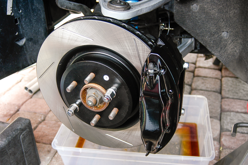
Bedding the Brakes
This is the last thing. You need to bed the brakes. This is done to get a coating of pad material on the rotor. If done right, you'll get the rotors to a nice blue tinge. There is shot with the color you are looking for:
Repeated from an earlier post/section:
I got that shot just after bedding the brakes. I took apart the setup to check everything, hence you see the calipers off the rear here. I did that to get a good look at the insides of the rotors.
The process to bed the brakes is relatively simple. You drive the car a bit to get the brakes warm. To do that you drive to about 30 or 40 MPH and slow the car gently to about 10 MPH but do not come to a complete stop. Do that 4 or 5 times and you warm things up. Once there, drive up to 60 MPH and then brake hard but not hard enough to engage ABS and slow the car down to 10 MPH. Immediately go back up to 60 MPH and brake hard again, going to 10 MPH but do not come to a complete stop. You will repeat the braking from 60 about 10 or 12 times never coming to a complete stop. After about 4 or 5 times, you will begin to get the scent of burning brakes pads. You may also feel some fade. Continue the process. This is what you want. You build up the heat and essentially coat the rotor with pad material. Once you have done it 10 to 12 times.... drive a bit and let the brakes cool. Drive at street speeds and try to avoid braking to a complete stop. Drive a about 5 minutes or so.
Once you've completed that sequence, do it again. Speed up and brake from 60 MPH to 10 MPH, hard, 10 to 12 times. Once done with the second time, you could do it a third if you'd like. I've usually been good after two cycles of this. The result is the blue tinged rotors. The brakes are now bedded.
The reason you do this is to get the best braking possible from the pads and rotor combination.
And that folks.... is that.Luis V.
Miami, Florida
2002 Dodge Viper GTS - FE #298 & 2013 Dodge Viper GTS
-
05-15-2014 #14Enthusiast
- Join Date
- Oct 2013
- Posts
- 4,693
Fantastic. I never knew what the specs for my Gen 3 brakes were - now I do. A great reference. Thank you,.
-
05-15-2014 #15Enthusiast
- Join Date
- Oct 2013
- Location
- Viper Drive, AZ
- Posts
- 793
Damn nice!
-
05-15-2014 #16Enthusiast
- Join Date
- Nov 2013
- Posts
- 1,711
Wow! That took a while to read. Good job!
-
05-15-2014 #17Enthusiast
- Join Date
- Oct 2013
- Location
- North Carolina
- Posts
- 1,235
Great how-to! Very lucid, excellent photos, and the end results look fantastic. Good description of bedding the pads to the rotors. Thank you!
-
05-15-2014 #18Enthusiast
- Join Date
- Jan 2014
- Location
- Michigan
- Posts
- 236
Beautiful. Thanks for the write up
-
05-16-2014 #19Enthusiast
- Join Date
- Oct 2013
- Posts
- 224
Very nice wrote up. You did a great job. Thanks for taking the time to post pics and info. I also did the brake up grade on my 1996 and love it.


-
05-16-2014 #20Enthusiast
- Join Date
- Oct 2013
- Location
- Cool, CA
- Posts
- 29
Nicely done!
Regards,
Aaron
-
05-16-2014 #21V1P3RGuest
Great write up! Very helpful and useful. Thanks for sharing!
-
05-16-2014 #22Enthusiast
- Join Date
- Oct 2013
- Location
- NoCO
- Posts
- 34
Did mine a few years back as well.
-
02-15-2017 #23Enthusiast
- Join Date
- Feb 2017
- Location
- montreal
- Posts
- 4
beautiful brake and wheel set-up Originally Posted by Detlef
;-)
-
04-24-2017 #24Enthusiast
- Join Date
- Jan 2017
- Posts
- 26
Beautiful car. This is exactly the same setup I want to upgrade my 97 GTS. I wish I was more car savvy. Thanks
-
05-16-2014 #25Enthusiast
- Join Date
- Oct 2013
- Location
- The True North Strong and Free Ontario, Canada
- Posts
- 1,635
Which kit from whom (vendor) or do you buy from wrecked Gen 3 or 4 and then buy the extra pieces needed or is there a whole kit that saves you time and money. What is the best and most cost effective way of putting something like this together


 Reply With Quote


Bookmarks