Measuring and Adjusting Backlash
Backlash is one of the many critical measurements that needs to be made when setting up a ring and pinion in a differential.
Backlash is simply the amount of play between the gear teeth of the ring and pinion. During normal operation, the differential heats up due to friction. Heat causes the gears to expand – having the proper amount of backlash between the gears allows for this expansion, and also allows the gear oil to work between the teeth to help prevent wear and keep them within their proper operating temperature range. Too little backlash can cause excessive heat build-up as the teeth get jammed together due to expansion, which in turn squeezes the gear oil out. At a minimum, the gears will be noisy. Too much heat build-up can cause the oil to break down, ultimately leading to metal-on-metal contact that results in excessive wear and permanent damage to the gears and/or bearings. Too much backlash is equally bad - the gears will likely be noisy (whirring, roaring, and/or clunking), and could also be damaged during operation as the gear teeth slam back and forth against each other during acceleration/deceleration. In either case, you’ll be looking at another rebuild. Good for experience; not so good for your wallet.
The amount of backlash required is a function of the differential design and gear manufacturing process. The backlash spec range for the Viper’s Dana Super 44 using OEM 2-cut Dana Spicer gears is 0.004-0.006” (source: 2008-2010 Viper Service manual provided by 13COBRA). For aftermarket gears, I’ve seen specs anywhere from 0.006-0.012”. If in doubt, call the gear manufacturer (or for the Viper, Unitrax). For some gear sets, it may even be scribed somewhere on the ring or pinion gears. If all else fails, here is another resource that will give you a backlash spec starting point for aftermarket 2-cut gears, but I can’t verify the accuracy of the information: https://www.differentials.com/wp-con...structions.png
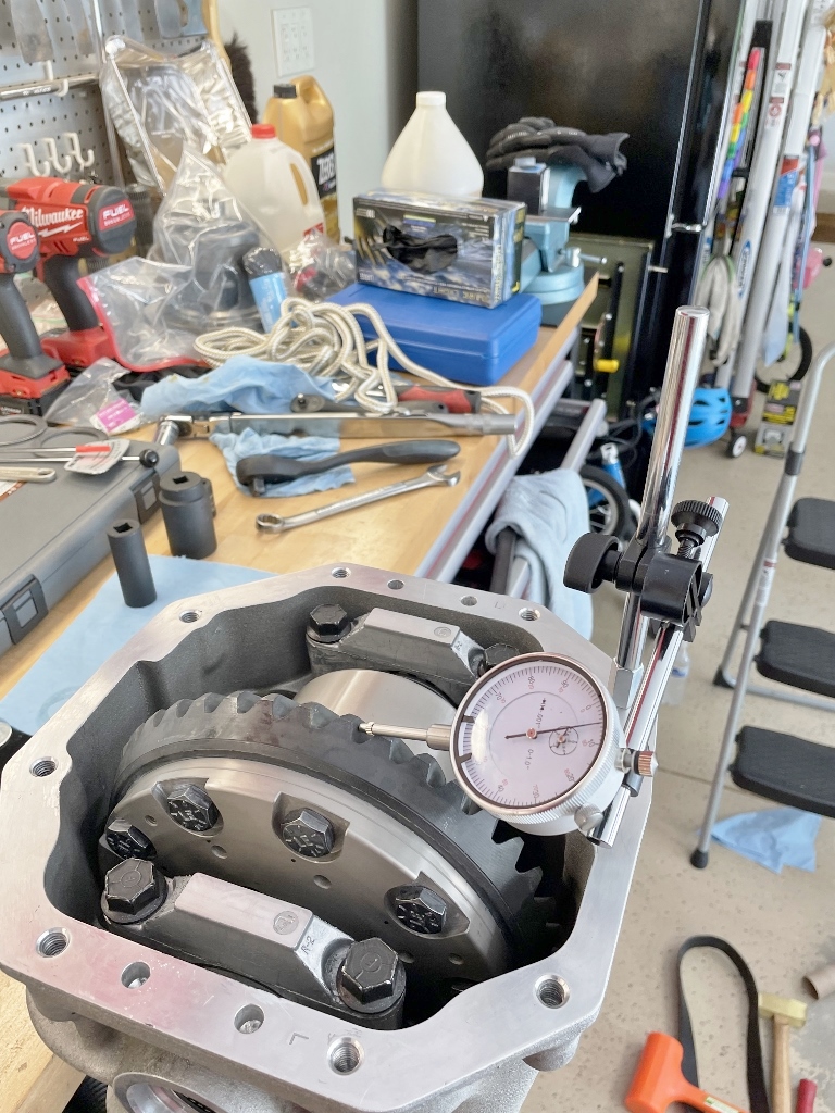
Measuring backlash requires a dial indicator gauge and a little bit of patience. It’s a little awkward at first, but once you get the hang of it, it’ll go pretty quickly for each setup you try. The most important thing is consistency – making sure the dial indicator is stable is paramount, followed by making sure the pinion gear cannot move during your measurements. That’s why I spent so much time and energy putting together something that allowed me to screw the base of the dial indicator’s adjustable arms directly into the aluminum differential case. If the dial indicator setup is allowed to move at all, you will not get consistent results. The same can be said for pinion rotation – any amount of pinion rotation during backlash measurements will lead to inconsistencies.
In order to get good, repeatable measurements, you need to make sure the plunger of the dial indicator sits square against the drive side heel of the ring gear tooth being measured in the plane of rotation. It’ll look something like this:
Once the adjustable arms and dial indicator are set, hold the pinion gear tight - that’s why you see my makeshift breaker bar jammed against my tool box. Grab the ring gear with your hand, and gently rock it back and forth. Assuming you have any amount of backlash, you’ll hear a nice “click clack” as the drive and coast side of the ring and pinion teeth make contact with each other. Most dial gauges can be zeroed out, but you don’t need to bother doing that here – all you need to do is watch how the needle of the dial indicator sweeps back and forth. As an example, if the needle moves back and forth across 5 tick marks on the dial indicator, you have 0.005” of backlash.
Here's the important part: you won’t be taking just one measurement. Each tooth of the ring and pinion gears is machined slightly differently, so it stands to reason that the backlash measurements will also vary slightly as different teeth are engaged. You’ll want to take at least 10 measurements at different teeth around the ring gear to get an average backlash measurement. If you are hard core, you’ll measure every other ring gear tooth. What you are looking for are any outliers – ideally, you want all backlash measurements to fall within specification, with the highest and lowest readings varying no more than 0.002”. If they vary more than that, it could be indicative of problems with how the gears were machined, or with the differential case itself. More than likely, though, it’s an issue with your gear setup and measurement process. As an example, not having enough pinion or carrier bearing preload would cause the gears to shift around as you are pulling on them, leading to inconsistent backlash measurements.
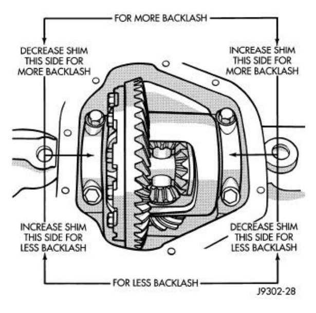
The carrier shims wedged between the carrier bearing cups and the differential case are used to adjust backlash on the Dana Super 44. As a reminder, the carrier shims also set the carrier bearing preload. The total carrier shim thickness (i.e., the left carrier shim thickness + the right carrier shim thickness) determines carrier bearing preload; the difference in thickness between the left and right shims sets the backlash. This diagram from the service manual will hopefully help:
Again, this will be an iterative process. Acceptable carrier bearing preload covers a range, as does backlash – once you know approximately how much total shim thickness gives the desired bearing preload, you’ll try to keep that value constant as you swap shim thicknesses left-to-right to get the backlash within spec. After a few setups, you’ll have a pretty good feel for what adjustments are needed to find that sweet spot. If you can’t seem to get there with the shims you have, you’ll need to order more until you do. Thousandths of an inch matter, and it’s worth doing right the first time. Anything less than within spec is not “good enough”.
Results 26 to 46 of 46
Thread: Viper Dana Super 44 Rebuild
-
10-29-2022 #26Enthusiast


- Join Date
- Oct 2013
- Location
- Dayton, OH
- Posts
- 4,803
Click Clack
Last edited by Steve M; 10-30-2022 at 10:14 PM.
-
10-29-2022 #27Enthusiast


- Join Date
- Oct 2013
- Location
- Dayton, OH
- Posts
- 4,803
You Spin Me Right Round
Measuring Ring Gear Runout
This one will be quick.
Checking ring gear runout requires the same tools as above (dial indicator gauge), only instead of putting the plunger against the ring gear teeth, you’ll be placing it against the back side of the ring gear. There’s a small lip you are aiming for – it doesn’t really matter where you catch it as long as the dial indicator gauge is perpendicular to the back side of the ring gear and the plunger can move freely. It should look something like this:
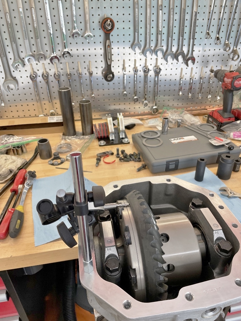
Once the gauge is set, all you have to do is rotate the pinion gear by hand and watch the needle. It’ll fluctuate a little as the ring gear rotates around – what you are looking for are the highest and lowest values the needle sweeps across.
The service manual spec calls for no more than 0.002” of runout. As long as you are below that number, you are good to go. Mine measured 0.001” for both the OEM setup as well as this new one.
If your ring gear runout measures outside of this spec, you'll need to figure out why. Here are some possible causes:
1. Burrs on the back side of the ring gear
2. Burrs on the carrier mating face (i.e., where the ring gear seats)
3. Ring gear not seated properly
4. Ring gear bolts not torqued properly
5. Improperly machined ring gear
6. Warped ring gear
7. Improperly machined carrier
8. Warped carrier
9. Improperly machined differential case
10. Warped differential case
11. Not enough carrier bearing preload
12. Not enough pinion bearing preload
13. Carrier bearings not properly seated
14. Carrier shims not properly seated
15. Loose carrier bearing caps
As long as you are using quality parts, do the proper prep work (e.g. deburring the ring gear with a file), and follow the procedures outlined above in the Basic Gear Pattern Setup Process, I wouldn’t anticipate any issues meeting the ring gear runout spec. Again, unless you are doing something wrong, this value shouldn’t change, so once you measure it (assuming it's within spec), you shouldn’t have to do it again.Last edited by Steve M; 10-30-2022 at 03:45 PM.
-
10-30-2022 #28Enthusiast


- Join Date
- Oct 2013
- Location
- Dayton, OH
- Posts
- 4,803
The Key to Success
How to Get Easy-to-Read Gear Patterns
If you only pay attention to one thing in this lengthy thread, this is it.
Get this part wrong, and you’ll be chasing your tail endlessly trying to figure out if your pinion depth is correct. This is the voice of experience speaking, so for the love of God and all that is holy, please listen.
Leading up to this project, I spent hours scouring the internet searching for differential setup advice, tricks, tips, and general wisdom. It seemed like those struggling the most with ring and pinion setups were having issues interpreting their gear patterns. The pictures they posted told the story, and it was usually quite confusing - for the most part, you couldn’t tell what was going on. There were no clearly defined areas that showed where the gears were making contact; it just looked like some paint had been smudged around, and that was about it. If you can’t see clearly defined patterns on the ring gear teeth where the paint was rubbed off by the pinion gear teeth (which will be where they primarily made contact), you won’t be able to tell what adjustments need to be made to get your pinion depth set exactly where it needs to be.
There’s no shortage of advice on how to do it correctly – YouTube, internet forums, aftermarket differential parts supply websites, take your pick. I tried a few different methods, and came up with one that worked for me. The key here is repeatability – when you find something that works, you need to do it exactly the same every time or you’re gonna be in for a long weekend (or 6, as was the case with my rebuild).
Here’s my advice on how to do it “right” – again, not an expert, so take it or leave it as you see fit, but if I had known the information I’m about to share with you, it would have saved me many, many hours of aggravation and the fitful nights of sleep that came along with it.
Step 1. Use the correct gear marking compound
The master install kit that came with my gears did not include gear marking compound. I’m not sure why it didn’t, but you will definitely need it. I had some white gear marking compound in my stash of random car stuff that I had purchased from Summit Racing many, many years ago. It was still good, so I decided to start with that. Some folks raved about GM’s gear marking compound (https://www.amazon.com/ACDelco-10-50.../dp/B007Q10TES) – AC Delco part number 1052351, referred to as GM Original Equipment 10-5055 Gear Marking Compound. I’ve also seen AC Delco part number 1152615 associated with the same product. Either way, it’ll come in a nondescript white tube with black letters, and the gear marking compound will be yellow. I tried it, but I didn’t find it to be any better than the generic Summit Racing stuff I already had. If you do buy some, one tube will have enough compound to run gear patterns all day every day until the end of time. Okay, maybe not that many, but a little bit goes a long way with this stuff.
Proper gear marking compound will be hydrated ferric oxide-based, and will wipe off somewhat easily without smearing. You must use a color that contrasts well with the ring gear finish – Dana Spicer gears have a matte black-finish (as do most aftermarket gears), so white or yellow are good choices. I’ve seen others recommend Permatex Prussian Blue fitting compound (this stuff: https://www.amazon.com/Permatex-8003...dp/B000HBM86Q/), but I would not use this product unless I was installing REM treated gears, which have a highly polished finish. Otherwise, dark blue on matte black just doesn’t provide enough contrast to tell what’s going on, at least not easily.
Here's a free tip: I found that adding a small amount of gear oil (like a single drop) to a small amount of gear marking compound (like a good paint brush full) and mixing it well before applying it to the ring gear teeth really helps generate clearly defined gear patterns. The small amount of oil thins out the compound just enough to help it wipe off even more cleanly. Just don’t go overboard – you don’t want runny gear marking compound.
Step 2. Apply the gear marking compound
Now you need a small paint brush, and a steady hand. I keep a pack of assorted paint brushes in my tool box for just such occasions, specifically these: https://www.walmart.com/ip/Assorted-...iece/193840762. I found that synthetic brushes worked the best.
Paint about 4 ring gear teeth on both the drive and coast side. Apply the compound so that it covers the teeth both evenly and completely - don't just glob it on. Done properly, it should look something like this:
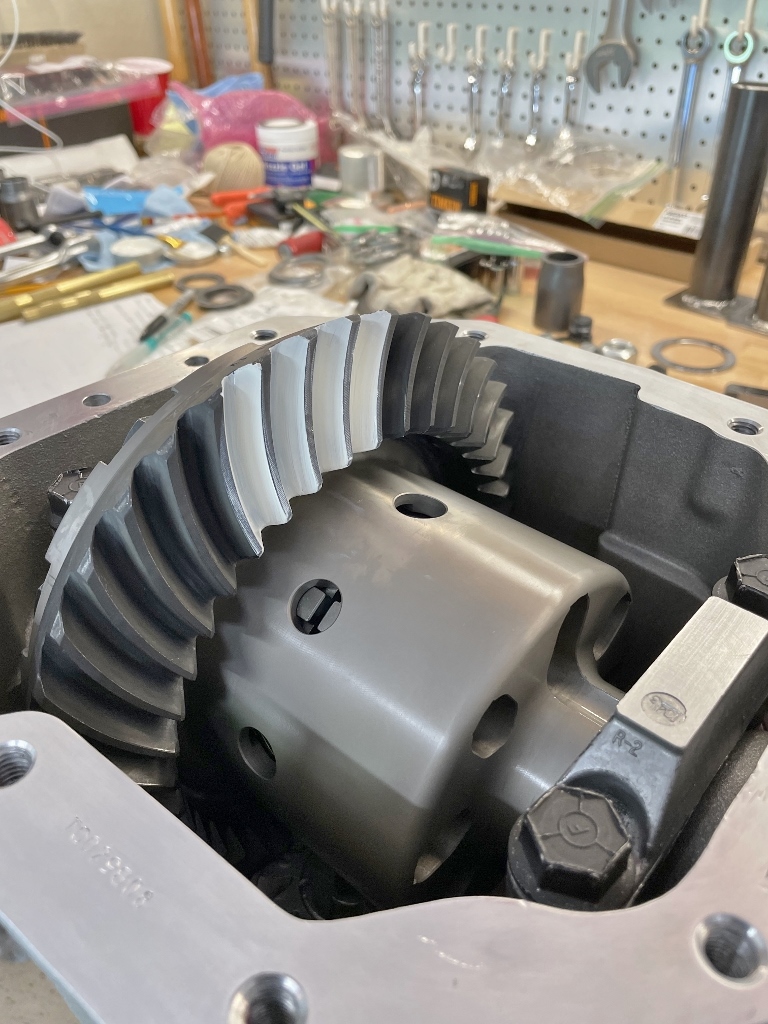
I found that wiping the compound off of the face (top land) of the ring gear teeth after painting them but before running the gears together helped me to see clearly where the wear pattern fell on the teeth between the face and flank, especially later on when I went back to look at the pictures I took of each pattern/setup to compare. And yes, you should take plenty of pictures (and label them!) to help you keep track of each setup you try.
Ideally, you’ll want to paint teeth at 2 or 3 different locations around the ring gear to ensure consistency and verify that you are doing things correctly. As I stated in one of my previous posts in this thread, however, I found this step to be overkill. As long as your ring gear runout is within spec and your backlash measurements have little to no variance (i.e., your backlash measurements for each setup are all within 0.001-0.002” of each other), you can probably get away with painting just one section of ring gear teeth. I’d still recommend painting multiple sections of ring gear teeth at least once, though, to prove it to yourself, especially if you get unexpected results.
Step 3. Apply load to the yoke
This step is critical. If you don’t apply a load to the gears while you turn them, you will get misleading and/or hard-to-interpret gear patterns. And when I say “load”, that means you need to figure out some way to add drag to either the pinion or ring gear.
I’ve seen lots of suggestions on how to do this – wrap a shop towel around the yoke, wedge a piece of wood against the ring gear, jam a pry bar against the ring gear, use a leather glove against the ring gear, etc. If you are working on a differential that’s still installed in the car, you might even be able to apply the brakes while someone else turns the ring gear. That’s not an option with a Viper, so you can dismiss that one immediately.
I tried most of the suggestions above – here’s what I didn’t like about each:
- Shop towel around yoke: it applied drag, but it chewed up a couple of my shop towels in the process
- Piece of wood against ring gear: it applied drag, but it also chewed up the piece of wood, which left wood particles in the housing
- Pry bar against ring gear: I wasn’t able to find a way to do this without gouging up the aluminum differential housing
- Leather glove against ring gear: it applied drag, but it also chewed up my leather glove, which left leather particles in the housing
Something wrapped around the yoke seemed like the best option for applying drag without the possible drawback of leaving leather/wood particles in the housing. The last thing you want is foreign debris that gets into either the carrier/limited slip unit or the bearings, possibly both. But what could I use instead of a shop towel?
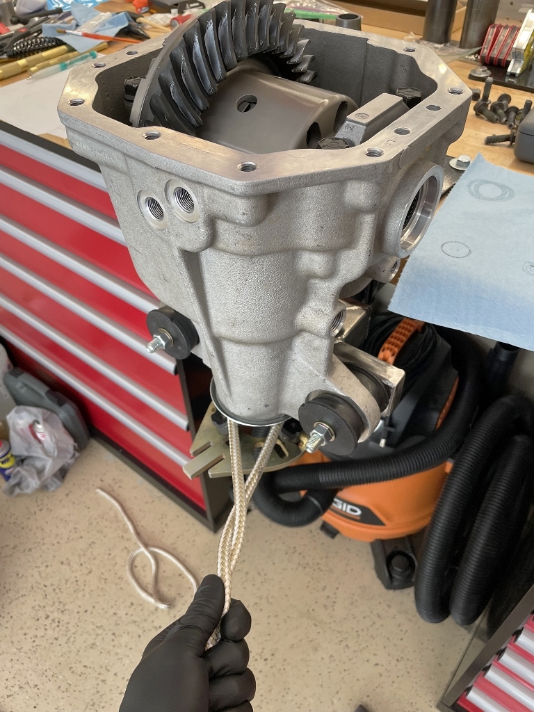
The best option I found was a 3/8" diameter, 15 ft. long piece of double braid nylon rope, available here: https://www.homedepot.com/p/Everbilt...0682/205804734
It wraps around the yoke nicely where the yoke meets the dust shield, and it is super durable. The nylon is slick enough to still allow the yoke to spin under load, but strong enough that you can apply your entire body weight against it without fear that it’s going to break (working load limit is 370 pounds). It should look something like this:
Step 4. Turn the RING GEAR
This step is also critical.
Do not use the yoke to turn the ring and pinion gears. Yes, it is convenient, and yes, it certainly turns the gears, but doing so will not give you the desired results. And whatever you do, do not use a drill (or worse, an impact gun) to spin the yoke by the pinion nut. If you do, you risk overtightening the nut turning it one direction, which will in turn add too much preload to the pinion bearings (reminder: there’s no crush sleeve installed at this point); in the opposite direction, the pinion nut will come loose, which will in turn remove the required pinion bearing preload (reminder: we are using a regular nut for gear setups at this point instead of the prevailing torque nut required during final assembly).
You must turn the assembly using a 3/4" box end wrench on the ring gear bolts. Apply a load to the gears by pulling sideways on the nylon rope wrapped around the yoke (Step 3), and with your other hand, use a box end wrench on the ring gear bolts to turn the ring gear 4 full revolutions in one direction, and then turn it 4 full revolutions the opposite direction. You'll have to do this in increments since you can only access a few ring gear bolts at a time, but just keep turning it until you get there. This will give you the required drive and coast patterns ready for the dark art of interpretation. It should be a bit of a workout – it was about 90 degrees in my garage while I was doing this, and I was sweating bullets by the time I was done.
Below is an example of two gear patterns generated using two different methods to turn the gears. The picture on the left was made by turning the yoke, and the picture on the right by turning the ring gear. The same pinion and carrier shims were used for both setups, the same load was applied with the rope, etc. The only difference was turning the yoke vs. turning the ring gear.
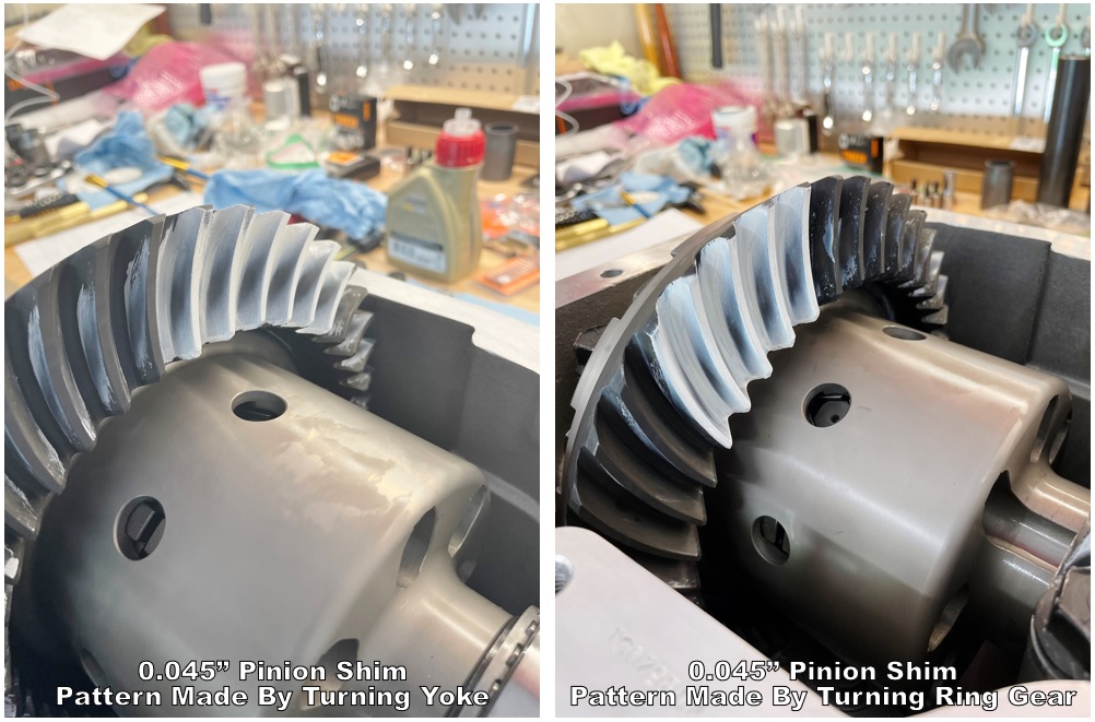
Both drive patterns shown used a 0.045” thick pinion shim. The picture on the left (made by turning the yoke) looks decent – maybe a bit deep, but the pattern is kinda centered face-to-flank. The picture on the right (made by turning the ring gear) tells a different story – the pinion is clearly too deep on the ring gear (the pattern is biased to the flank of the ring gear tooth). The added drag from turning the ring gear by the bolts made a significant difference.
And here is another example – same as above, only using a 0.042” thick pinion shim to help pull the pattern up out of the flank/root.

The drive pattern on the left looks kinda okay, but I’m getting mixed messages; 3 teeth are telling me it may be a bit deep, and the other two teeth look pretty good. The picture on the right says we are pretty darn close – all teeth are saying “I wouldn’t go any shallower.” This is where we would need to reference the coast side for a second opinion.
I realize some of this probably doesn’t make sense, but give me a few more posts and I’ll try to explain why I was having so many issues interpreting these gear patterns, especially on the coast side.
-
10-30-2022 #29Enthusiast


- Join Date
- Oct 2013
- Location
- Dayton, OH
- Posts
- 4,803
What the hell is even that
2-Cut (Face Hobbed) vs. 5-Cut (Face Milled) Gears
This little bit of info could have saved me so many headaches.
I’ve mentioned 2-cut vs. 5-cut gears throughout this thread, but until now I haven’t shown what the differences are, and more importantly, why it matters.
Here’s a pretty good description (source: https://www.differentials.com/two-cu...ive-cut-gears/, emphasis added is mine):
“The terms Two Cut and Five Cut refer to the machining process used to manufacture Ring and Pinion gear sets. Traditional ring and pinion gears were manufactured using a Five-Cut process (Face Milling). Most current manufacturing methods use a Two-Cut process [Face Hobbing] that only requires about 30% of the traditional manufacturing time. Each process results in a different gear tooth profile, and slightly different method for setup.”
Here are a couple of pictures that illustrate the differences in the gear tooth profile:
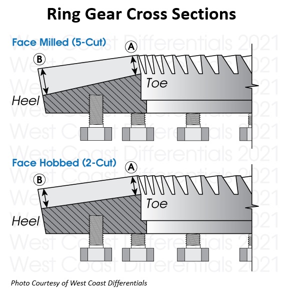
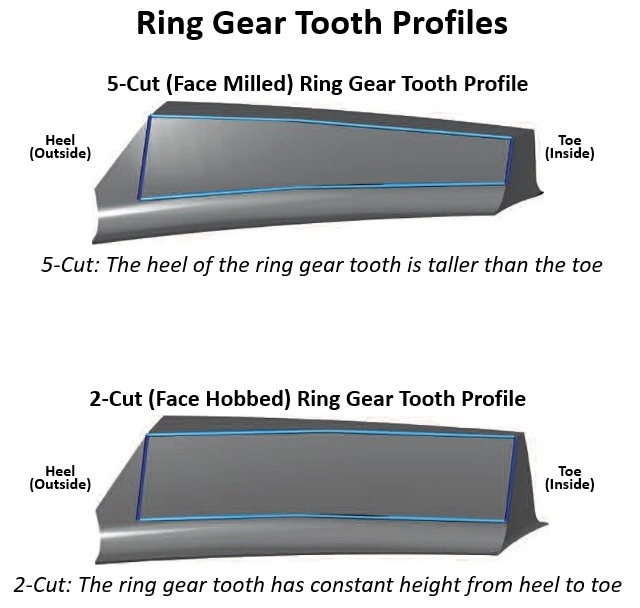
Image sources:
https://www.differentials.com/two-cu...ive-cut-gears/
https://www.revolutiongear.com/2_cut_vs_5_cut_gears
And here is a video showing the two side-by-side:
Once you know what to look for, it’s pretty easy to tell the difference. Unfortunately, I didn’t know anything about this until I was over 10 hours into this little project.
Many OEM manufacturers, including Dana Spicer, have gone to the 2-cut machining process – a ~70% savings in manufacturing time is huge in a mass production environment, and there don’t appear to be any drawbacks in terms of durability or added gear noise (i.e., they are just as strong, and run equally quiet when set up properly).
The major difference between the two, and what really matters here, is that the gear patterns of a 2-cut vs. a 5-cut gear set look totally different. Revolution Gear hints at this when they state on their website “2-Cut Gears also have a natural "bias" condition; that is, the pattern shows up slanted when the pattern is rolled with gear marking compound.”
Huh?

Hang on...I’ll show you.
-
10-30-2022 #30Enthusiast


- Join Date
- Oct 2013
- Posts
- 3,749
Steve, THANKS for the efforts that you put forth in this remarkable writeup. CONGRATS for making this one of the most complete and well illustrated "how to" threads that we have seen here !!
Fear not...I won't be trying this myself...but you have indeed made it look "doable".
Will this thread be coming out later in hardback or paperback editions ??
-
10-30-2022 #31Enthusiast


- Join Date
- Oct 2013
- Location
- Dayton, OH
- Posts
- 4,803
When I took on this project, I never intended to do a full write-up since Bryan Cowger did such a good job on his so many years ago. I just learned so many lessons along the way of my own journey that I felt like keeping it to myself wasn't the right thing to do. This is the first time I've done most of the writing in a stand-alone Word document, mainly so that the knowledge is captured somewhere on the off chance something happens to the forum database. At this point, I'm up to 44 pages of text only - the pics are all hosted through a 3rd party website, but all the originals are on my hard drive as well. They're even somewhat organized. I'm getting close to the end, but this story has a twist (quite literally), the details of which I'll get to all in good time...
I'd think about publishing if I had any credibility in the differential rebuilding world, but I'm missing about 20 years of experience. If I ever do, though, I'll send you a signed copy (hardback) on the house as a thank you for your kind words. Most will just have to settle for the service manual, and a little less detail than you really need to get this job done.
-
10-30-2022 #32Enthusiast


- Join Date
- Oct 2013
- Location
- Dayton, OH
- Posts
- 4,803
Makes me want a hamburger
5-Cut Gear Pattern Examples
I’ll try not to spend too much time here since the gears I used were of the 2-cut (face hobbed) variety, so most of this won’t apply to what I did.
Most gear pattern examples out there on the internet represent patterns for 5-cut (face milled) gears. With the proper pinion depth, you should see a nice oval pattern on both the drive and coast side of the ring gear teeth. It is important to note that the pattern may not be centered between the heel and toe of the tooth – as long as the backlash is correct, there really isn’t much you’ll be able to do about it. Here are examples of acceptable patterns (source: https://www.yukongear.com/blogs/how-...ear-patterns_1):
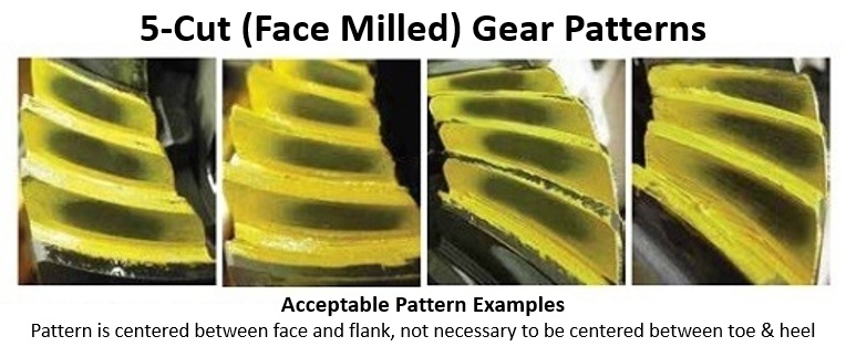
Keep in mind that these patterns were run on new gears. If you are installing used gears, you may not be able to get a good pattern on the drive side since that will have the most wear. In that case, you’ll have to rely on the coast pattern to verify correct pinion depth.
If the pattern is too shallow, it’ll be too high up on the gear tooth. If it is too deep, it’ll look like it is coming up out of the root. Here are a couple examples showing both conditions from the same source referenced above:

To fix a pattern that is too shallow, you’ll need to increase the pinion shim thickness and try again. If the pattern is too deep, you’ll need to decrease the pinion shim thickness.
Pretty simple, right? Especially now that you know how to generate easy-to-read gear patterns.
But there’s one more piece of information you can use with 5-cut gears to figure out whether or not your pinion depth is correct, and that is by interpreting the pattern that shows up on the pinion gear. I learned about this technique here: http://gearinstalls.com/
That website is the only place I’ve ever seen this technique mentioned. The pinion gear pattern you are looking at is essentially a comet, and you are specifically looking at where the comet tail falls on the pinion gear tooth. This is what I’m talking about (circled in black and shaded slightly red in the right picture for emphasis - source: http://gearinstalls.com/):
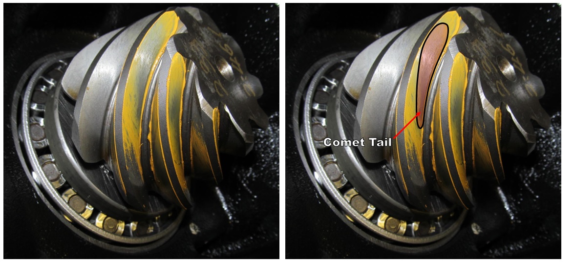
The important thing to note is that the comet tail pattern will be opposite to what the ring gear pattern shows. If the ring gear pattern is too deep, the pinion pattern will appear too shallow. If the ring gear pattern is too shallow, the comet tail will appear too deep (it’ll be tucked into the root of the pinion gear). Ideal pinion depth will put the comet tail about half way between the center of the pinion gear tooth and the root. This picture should hopefully help explain the concept better than my words:

And here’s just one example from that same website that puts it all together:

In the top 3 pictures, the drive and coast patterns look pretty good, but the comet tail says it is too shallow. He added a little more pinion shim thickness, and ended up with the bottom 3 pictures which ended up being the final setup for those gears. The comet tail came out of the root on the pinion gear tooth and was feathering toward the center, which is about ideal. It should be noted that many installers will run the pinion slightly deep – that is preferred for heavy duty applications since heavy loads will try to pull the gears apart. If the gears are set up a little deep, it’ll still leave you with lots of tooth contact area under load (think towing something heavy with a truck).
If you want to learn a lot, peruse the Gear Installs website. It is mostly dedicated to Toyota products, but he deals with lots of different designs and challenges, and has pictures that show pretty much every step along the way. The guy that created and maintains that website is who ended up helping me out in my time of need – I sent him an email out of the blue when I got stuck, and he responded within a day. He was incredibly generous with his time and insights, ultimately helping me be successful with my little endeavor. I don’t know if he’ll ever see this post, but if he does, thanks Ken…you are a class act!
In summary, with 5-cut (face milled) gears, you have three sources of information to help you determine proper pinion depth:
1. Drive side pattern (ring gear)
2. Coast side pattern (ring gear)
3. Comet tail (pinion gear)
The drive side pattern is the most important, so if you can only get one thing right, focus on that one.
And for those trying to figure out the post title, go back and watch the video I linked to earlier in this thread (Reading Gear Patterns In Just 3 Steps) that relates 5-cut gear patterns to hamburger buns.Last edited by Steve M; 12-23-2022 at 11:44 AM.
-
12-23-2022 #33Enthusiast


- Join Date
- Oct 2013
- Location
- Dayton, OH
- Posts
- 4,803
No hamburger for you
2-Cut Gear Pattern Examples
Throughout most of this process, I thought my coast patterns were total garbage – I couldn’t tell what was going on. I didn’t even take pictures of most of them because they weren’t telling me anything useful (or so I thought). They weren’t centered, they weren’t oval...they were nothing like you see in the gear pattern charts available online. It was the same but not quite as bad on the drive side. I eventually started wondering if the gears were defective.
What most online resources failed to mention is that 2-cut gear patterns look nothing like 5-cut gear patterns, especially on the coast side. I could have saved hours (like double-digit numbers of hours) had I known this, and had I also known that the gears I had were of the 2-cut variety.
West Coast Differentials at least took a swing at it, but only provided this diagram as an example of a 2-cut gear pattern (source: https://www.differentials.com/two-cu...ive-cut-gears/):
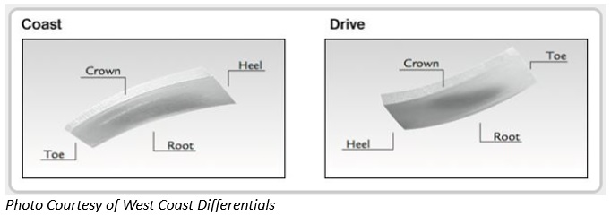
Not as helpful as they probably intended.
Yukon got a little closer to the mark with their diagrams (source: https://www.yukongear.com/web_images...Step-Gears.pdf):
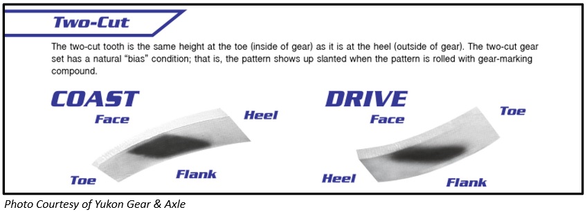
Note the term “bias”, also sometimes referred to as a “bias condition” or “bias pattern”. Basically, the pattern will look something like a parallelogram, or at least some sort of square-ish or rectangular-ish shape that is leaning over on both the drive and coast side.
The Yukon diagram shows ideal 2-cut gear patterns for both drive and coast.
Here’s the key to knowing when you are done: the ideal pattern will have face-to-flank symmetry.
What does that mean? Hopefully a few arrows and lines will help:

The width of the ideal 2-cut gear pattern should be the same at the face (top part of the gear tooth) and the flank (bottom or base of the gear tooth). All you have to do is find the right shim thickness to achieve that.
If the pinion is too deep, the pattern will be wider at the base of the tooth and narrower at the top. If it is too shallow, the pattern will be wider at the top of the tooth and narrower at the bottom.
If it is way too deep, it’ll look similar to a 5-cut gear pattern – basically like the sun is rising up out of the root. If it is way too shallow, the pattern will do the opposite - it’ll look like the sun is coming down from the top of the tooth.
Based on my limited experience, the drive side pattern came in to focus more quickly and clearly than the coast side pattern. Once I got the drive pattern close, the coast pattern helped me make small tweaks to get it just right.
It is important to note than the comet tail (the pattern on the pinion teeth) is not a reliable indicator for 2-cut gear patterns, so you only have two sources of information to help you determine proper pinion depth:
1. Drive side pattern (ring gear)
2. Coast side pattern (ring gear)
If you still don’t understand, fear not; more pics are on the way.
-
12-23-2022 #34Enthusiast


- Join Date
- Oct 2013
- Location
- Dayton, OH
- Posts
- 4,803
Like a Fish
Different Shim Combos and Results – Part 1
Now it’s time for you to bear witness to my floundering.
Important Note: All of the patterns you are about to see were the result of using my custom-made setup pinion bearing.
This first set of drive side patterns was generated by turning the pinion instead of the ring gear like I should have done. As a result, the patterns were ill-defined and inconsistent:
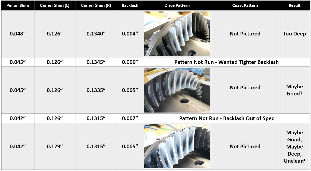
With the proper pressure applied to the yoke and by turning the ring gear by the bolts with a 3/4" box-end wrench, the 0.045” pinion shim went from being “Maybe Good?” to “Too Deep”:
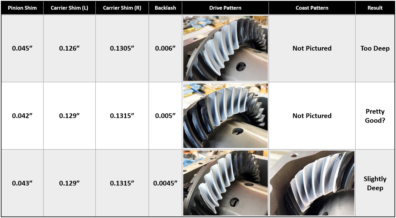
That is why you must follow each step laid out above in my “How to Get Easy-to-Read Gear Patterns” section.
And now you will start to see evidence of my lack of understanding of what I was looking at. The 0.042” thick pinion shim was just about right, but I was so confused by what I was seeing on the coast side that I ran thicker pinion shims instead, including the 0.044” thick shim twice:
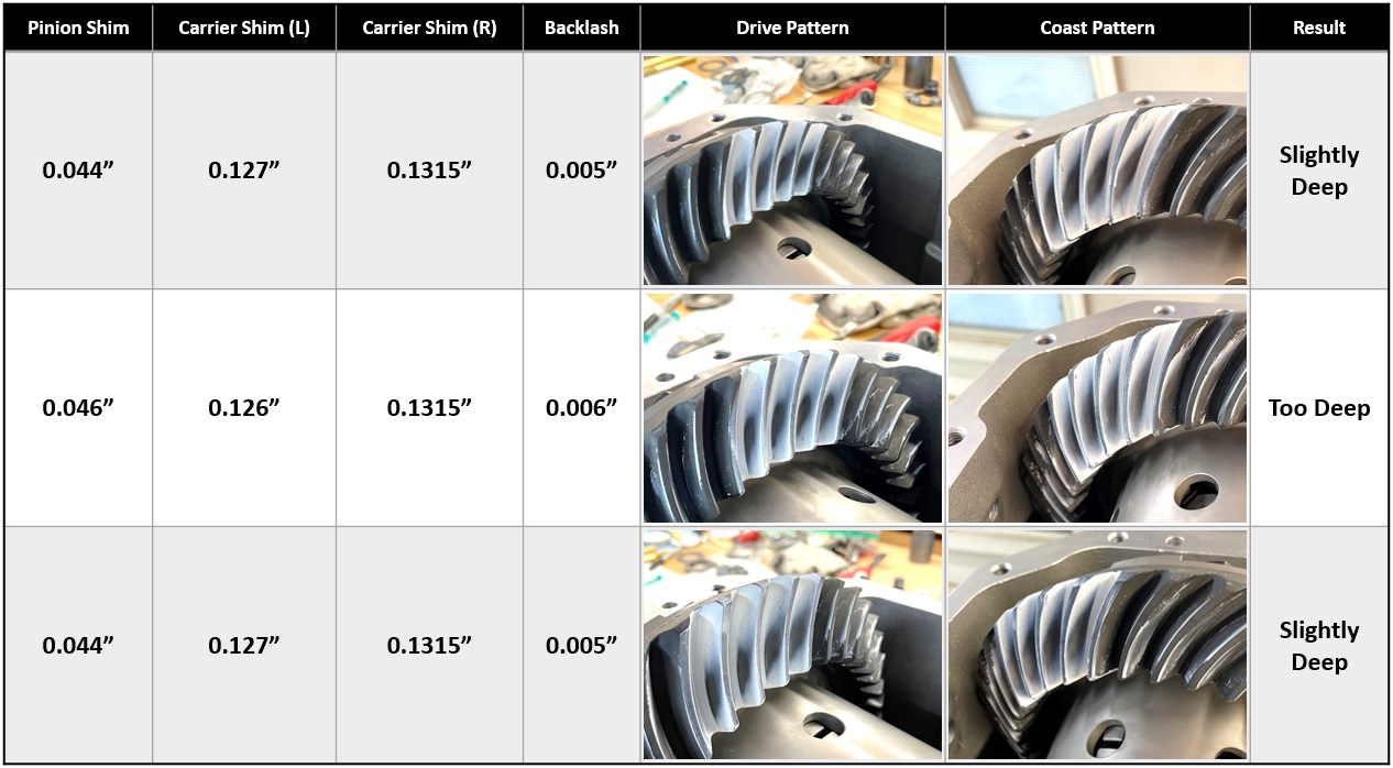
Clearly I was going the wrong direction, so I went back the other way with the pinion shims and came up with these:
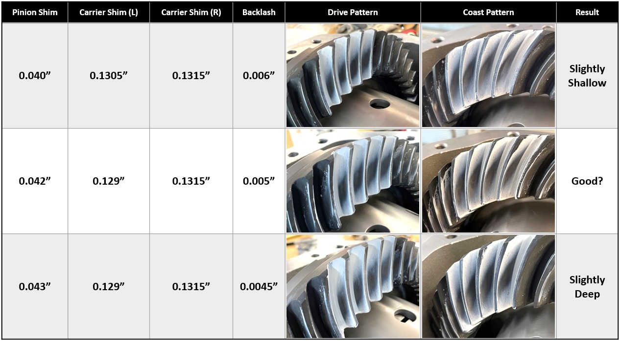
Although I didn't realize it at the time, I was finally able to manage a slightly shallow pattern with the 0.040" pinion shim.
Keep in mind that each of these setups took about an hour, so that was a lot of time (and sweat) invested, much of which I could have saved if I had just known the secrets of reading 2-cut gear patterns.
At this point, I decided to go with the 0.043” pinion shim as the starting point for my final setup with a pressed-on inner pinion bearing. This would place the pinion slightly deep on the ring gear, which is generally preferred for gears that will be subjected to heavy loading.
-
12-23-2022 #35Enthusiast


- Join Date
- Oct 2013
- Location
- Dayton, OH
- Posts
- 4,803
All aboard the fail boat
Where My Setup Bearing Failed (And Why)
To recap, I went through many different iterations with my setup pinion bearing (the one that just slips on and off without the need for a press), and decided to try the 0.043” pinion shim for what I thought would be my final setup.
I slapped on the 0.043” pinion shim along with my brand-new Timken inner pinion bearing, and into the press it went (along with my custom-made bearing press adapter/tool):
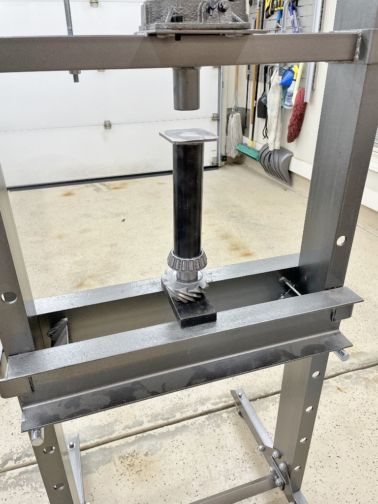
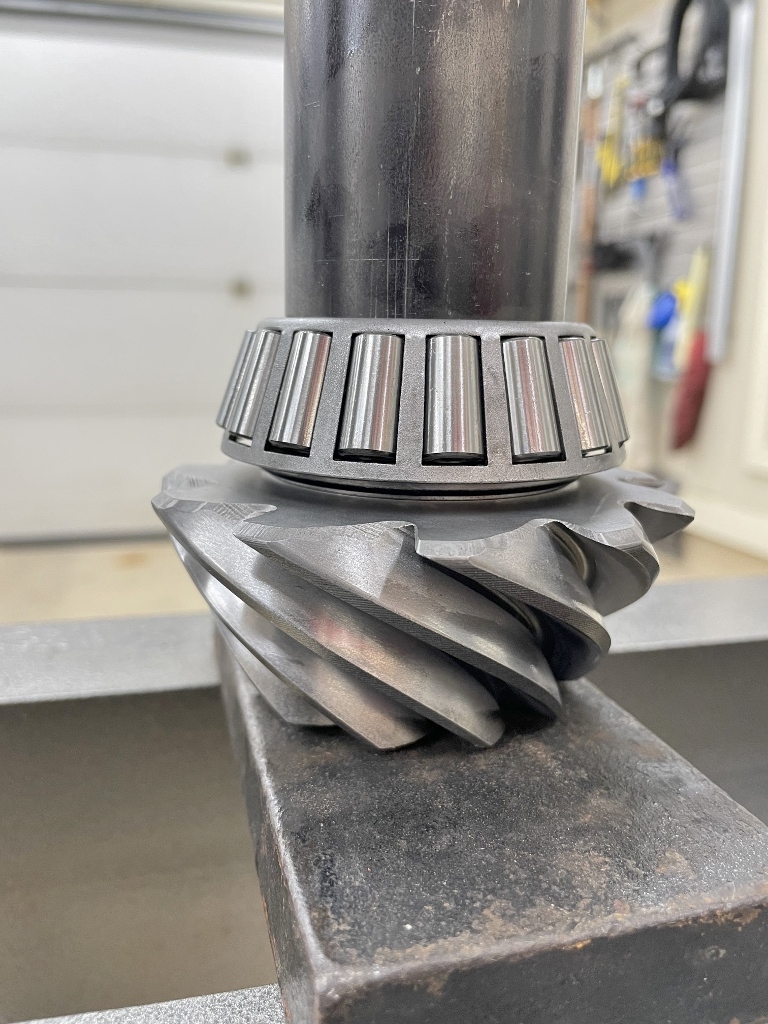
Bitchin.
Little did I know that I was in for a large serving of humble pie sprinkled with a bit of rage. Holy shit I was pissed.
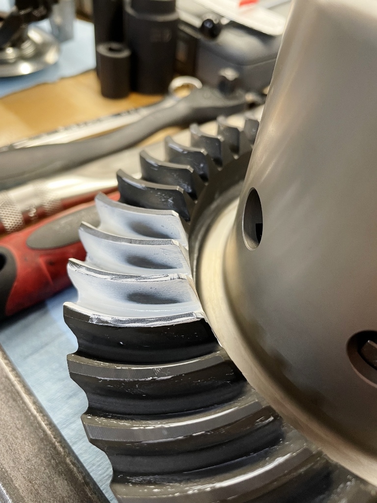
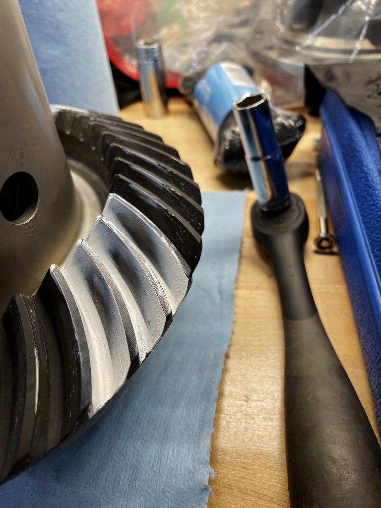
The first clue that something was off was the backlash measurement. I previously achieved the proper backlash spec (0.004-0.005”) for a 0.043” pinion shim by using 0.129” left and 0.1315” right carrier shims. That same carrier shim combination with the pressed-on inner pinion bearing (and the same pinion shim) resulted in 0.001-0.002” of backlash. That was way tighter than I expected; in hindsight, I should have immediately known that the pinion was too deep on the ring gear.
I swapped out the left-hand carrier shim for one that was 0.126”, leaving the right-hand carrier shim the same (0.1315") – that gave me 0.004” of backlash. Tight, but within spec. I then proceeded to run the gear pattern and came up with this:
Drive:
Coast:
Well shit.
The pattern went from being slightly deep to definitely too deep.
Why?
This is my theory: the inner pinion race has to expand ever-so-slightly when the inner pinion bearing gets pressed on the pinion shaft – that’s what holds it in place. The tapered rollers consequently get pushed out as the inner race expands. That small change would ultimately affect how far the rollers seat into the matching tapered cup that is pressed into the differential housing; they would sit a bit proud, effectively pushing the pinion gear teeth toward the ring gear centerline, causing a deep(er) pattern.
What backs my theory is that with no other changes, the pressed-on bearing tightened up the backlash significantly, which is indicative of a deeper mesh. The pattern proved that it was indeed too deep. The results were also consistent and repeatable. Based on my previous findings (referencing the pics in the post above), I’d guess that the pinion was now about 0.003” too deep (it looks like the pattern generated with a 0.046” pinion shim in the post above).
Bottom line: was a setup bearing useful? Yes and no.
On the positive side, I was able to quickly swap out pinion shims without the need for a press or a clamshell bearing puller. That saved me at least some time, and I was able to gather a lot of good insights as to how each shim affected the overall setup. It was also consistent – I ran some shim combos multiple times, and the results with the setup bearing were the same each time.
On the negative side, I still had a lot of work ahead of me to find the correct pinion shim, but I was at least in the general ball park. Unfortunately, I now had to pull the bearing off and press it back in place without damaging it, which added a bit of stress since I only had one inner pinion bearing on hand.
Would I use a setup bearing if I had to do this over again?
Probably not.
It was good for a first-timer like me, but now that I have at least some experience, I’m not sure it would serve any purpose other than to get me within a few thousandths of the correct pinion shim thickness before whipping out the hydraulic press. If you'll remember, I did not have a hydraulic press on hand at the time (it was at my friend's house ~45 minutes away), so I was hoping I would only need it once. I've since learned that a hydraulic press is something you really need on-site throughout the entire process - don't fight it, just get (or borrow) one.
My recommendation also assumes that you can quickly and easily remove the pressed-on bearing without damaging it. It can be done, but you need the right tools on hand to do it (like a clamshell bearing puller). If you are reliant on a shop to do the pressing, a setup bearing would make a lot of sense, and would likely save you quite a few trips to and from the shop, but expecting it to be a one-and-done type of thing is probably unrealistic.
Your mileage may vary.
-
12-24-2022 #36Enthusiast


- Join Date
- Jan 2015
- Location
- Houston
- Posts
- 276
Really awesome watching you document your experience, thank you! And thank you for confirming that I won't be trying this myself.
-
12-24-2022 #37Enthusiast


- Join Date
- Oct 2013
- Location
- Dayton, OH
- Posts
- 4,803
-
12-24-2022 #38Enthusiast


- Join Date
- Oct 2013
- Posts
- 3,749
Hell, I see a post-retirement hobby business starting to take form.

Happy Holidays to You and Yours, Steve !!
-
12-24-2022 #39Enthusiast


- Join Date
- Oct 2013
- Location
- Dayton, OH
- Posts
- 4,803
-
12-24-2022 #40Enthusiast


- Join Date
- Oct 2013
- Location
- Dayton, OH
- Posts
- 4,803
I put the suck in success
Different Shim Combos and Results – Part 2
I took a few days off after that last round of disappointment, but it ended up being a good thing – it gave me a chance to clear my head and put a plan together to get the proper pinion depth with the pressed-on bearing.
Thankfully I already had the Mopar 0.040” – 0.044” Pinion Shim Kit (part number 04856369) on hand. The 0.043” shim was clearly too thick, so my plan was to try the 0.042”, 0.041”, and 0.040” shims and record the results. My clamshell bearing puller did a great job of removing the pressed-on pinion bearing without damaging anything, and the bearing went right back on with the 20-ton press (x3).
The results:
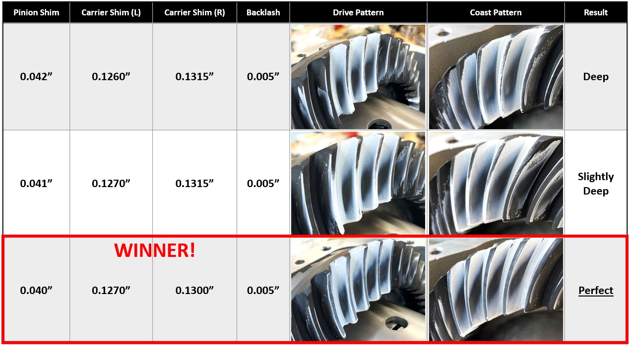
Looks like the 0.040” pinion shim was the winner. I also sought out a second opinion from the gentleman that owns http://gearinstalls.com/, and this is what he had to say:
“Oh yeah....I like that one......winner! That represents the perfect 2-cut paint pattern there....both the position and the 'symmetry'.”
Here’s another look at the 0.040” shim results, with a couple of lines showing the symmetry to which he refers:

Good enough for me.
I also asked if he preferred to run the pinion a little deep on the ring gear for better overall durability, and this was his response:
“In order to eliminate or greatly reduce any ‘noise issues’ with a lot of these super quiet late model Toyota trucks, I do aim for ‘exact depth’. Pretty much now stay away from too many of the ‘slight deep’ condition. The late model Tacoma gears, as an example, are sensitive to needing to be ‘exact depth’.....that's why a lot of them from other shops are noisy. They don't fine tune. But mine are quiet.”
Exact depth it is then.
In summary, I started with the original 0.048” shim, and ended with the 0.040” shim for this particular set of gears in this housing. For perspective, a sheet of standard printer paper is 0.004” thick. The difference between slightly deep and just right was 0.001”. That’s what I mean when I say the details matter – one-thousandth of an inch is less than the thickness of a human hair.
On to final assembly!
-
12-24-2022 #41Enthusiast


- Join Date
- Oct 2013
- Location
- Ontario,MCVO,PA,OH
- Posts
- 2,671
Great post as always Steve !
As an Enthusiast you've made significant contributions to this site , hopefully when they re vamp the site in the New Year someone takes that into account .
Merry Christmas to you and everyone on this site !!!
From The True White North .
-
12-26-2022 #42Enthusiast


- Join Date
- Oct 2014
- Location
- The Netherlands
- Posts
- 182
-
12-26-2022 #43Enthusiast


- Join Date
- Oct 2013
- Location
- Dayton, OH
- Posts
- 4,803
I guess that means I didn't meet my goal of making this project accessible to the masses.
I'll fully admit that there are some major barriers to rebuilding a differential. I spent most of my mental energy trying to figure out how to hold the housing so I could effectively work on everything. Once you get over that, the job only requires a few basic mechanical skills. There are very few parts associated with this project, and delicacy is not required. The key is consistency - you have to find a process that works for you that gets the job done, and then you just have to keep following it every time. You can see evidence of the maturation of my setup process with the gear patterns I showed above - my initial results were inconsistent, but that was entirely a process issue. Once I fixed that, everything started to make sense. The other big barrier is the expense of some of the specialty tools required for this job - there's not much anyone can do about that unfortunately.
The final key was figuring out how to interpret what I was seeing with the gear patterns. For that one, I'm certainly willing to take a look at anyone's gear pattern results if they'd like a second opinion.
It's not a job you are simply going to knock out in an afternoon, but I do feel like it is a project worth knowing how to do. I can't begin to describe the feeling you get when you go from a noisy ring and pinion to one that is completely silent. It is very rewarding, especially knowing that you are the one that made it that way.Last edited by Steve M; 12-26-2022 at 05:39 PM.
-
12-26-2022 #44Enthusiast


- Join Date
- Oct 2013
- Location
- Dayton, OH
- Posts
- 4,803
One last hurrah
Final Setup/Assembly
Time to up the pucker factor a little bit.
In theory, if your setup process is sound and you’ve been consistent, the final gear pattern generated should be exactly the same as what you just accomplished. There are some additional steps for final assembly, but if you’ve gotten this far, it’ll be nothing you can’t handle.
First, the service manual specs:
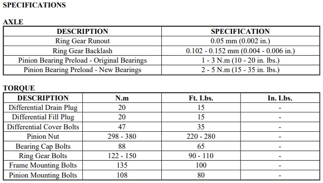
Let’s dig in!
Step 1. Remove gears from housing and clean off any gear marking compound
Remove the carrier bearing caps and bolts and set aside. Pull the carrier out of the differential housing and set the shims aside. Flip the housing over and remove the pinion. The pressed-on inner pinion bearing will stay in place this time – you’ve already found the correct pinion shim, so there’s no need to repeat any part of that process.
Clean off all gear marking compound from both the ring and pinion (I used brake cleaner). You’ll be running one final gear pattern check, and you don’t want any evidence of the previous pattern muddying the waters.
Step 2. Install output shaft seals
If you need to install new stub shaft support bearings, now is the time to do it. I left mine in place throughout the process, so I didn’t touch them.
Turn the housing on its side, grab your new output shaft seal, set it in place, grab the installation tool(s) of your choice (I used the specialty Miller tool # C-4026B + a hammer), and tap it in place. A large socket might also be able to be used in place of the Mopar tool.

The key is getting each seal started squarely – if it gets cocked to one side, it’ll make the seal hard to drive in place. It did take a fair amount of force to get it started, so don’t be afraid to do a little banging. That’s what I liked about the Mopar tool – the design protects the inner part of the seal from damage and ensures it is seated flush to the housing.
Once one seal is seated, flip the housing over and install the other.
This step can be saved until later in the final assembly process, but it is far easier to maneuver the differential into a more advantageous position without the carrier installed. The carrier + bearings + ring gear add a significant amount of unevenly distributed weight to the differential housing.
Step 3. Determine proper solid spacer shim stack (Optional)
If you are using a crush sleeve, this step is optional. If you are using a solid spacer, this step is not optional.
The solid spacer instructions recommend installing all of the supplied shims as a starting point:
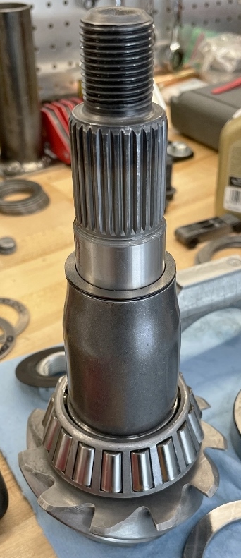
If the solid spacer was machined correctly, you shouldn’t end up with any preload no matter how much you tighten the pinion nut with all of the shims installed. I thought I’d be able to skip this step and get a little closer to the mark by using the old crush sleeve as a starting point for the shim stack, but it ultimately did not help.
This is another iterative process, so just pick a shim combo and give it a whirl. Write down the shim combo in your notes. The assembly order is as follows: pinion, pinion shim + inner bearing (already assembled/pressed in place), the solid spacer, and then the solid spacer shim stack. As always, oil the bearings first. Install the assembly into the housing, then slide the outer pinion bearing and yoke on from the other side. Do not install the oil slinger or pinion yoke seal yet. Slide the setup washer and pinion nut on the pinion shaft and tighten until the yoke and bearing are fully seated.
Now for the moment of truth. Grab your torque wrench, and start tightening the setup pinion nut down. I started at 100 ft-lbs. Measure the pinion preload as you are tightening. If it is anywhere under 15 in-lbs of torque to rotate, tighten the pinion nut some more. I went up in 25 ft-lb increments. Check the bearing preload at every increment. If the shim stack is correct, you’ll likely start getting some preload as you start approaching 150 ft-lbs of torque on the pinion nut. If the stack is too thick, you won’t have any preload. If the stack is too thin, you’ll have too much preload right off the bat.
As an example, I started off with a 0.035” shim stack. I tightened the setup pinion nut to 100 ft-lbs, and was immediately greeted with 40 in-lbs of torque to rotate – way too tight. If that happens, back the nut off, pull the yoke and washer off, remove the pinion from the housing, and try a thicker solid spacer shim stack. I tried a 0.051” shim stack next, and had no preload even at 150 ft-lbs of torque on the pinion nut.
After a few more iterations, I settled on a 0.048” thick shim stack (0.012” + 0.016” + 0.020” shims). That gave me 0 in-lbs of preload at 100 ft-lbs of torque on the pinion nut, 8 in-lbs @ 150 ft-lbs, 22 in-lbs @ 200 ft-lbs, 24 in-lbs @ 220 ft-lbs, and 27 in-lbs @ 250 ft-lbs of torque. That’s right about where I wanted to be for the pinion bearings.
Important note: pinion bearing preload comes on FAST. It’ll be nothing, nothing, nothing, and then boom – it hits. Spicer states that a 0.001” change in preload spacer thickness will change the torque to rotate approximately 30 in-lbs (source: https://media.spicerparts.com/cfs/fi...o/xmzz0551.pdf, pg. 15).
Once the preload is where you want it, remove the pinion nut, washer, and yoke and set aside. The pinion should still be held in place by the outer pinion bearing’s friction fit on the pinion shaft.
If using a crush sleeve to set the pinion bearing preload, this step is where you would install the crush sleeve.
Step 4. Install oil slinger

Step 5. Install pinion yoke seal
Now is the time to install your brand-new pinion yoke seal. Put a small amount of oil on the seal’s o-ring and set it in place. You can either tap it in with a hammer, or you can use the Mopar specialty tool (Miller part # 8889). The tool clears the pinion shaft and fits into the seal’s channel, allowing you to apply even pressure to the seal with either a hammer or a press as you drive it in place, minimizing the risk of damage to either the seal or pinion shaft. I’d recommend running a small bead of RTV sealant just under the outer lip of the pinion yoke seal – that should keep any oil that gets past the o-ring from going any further.
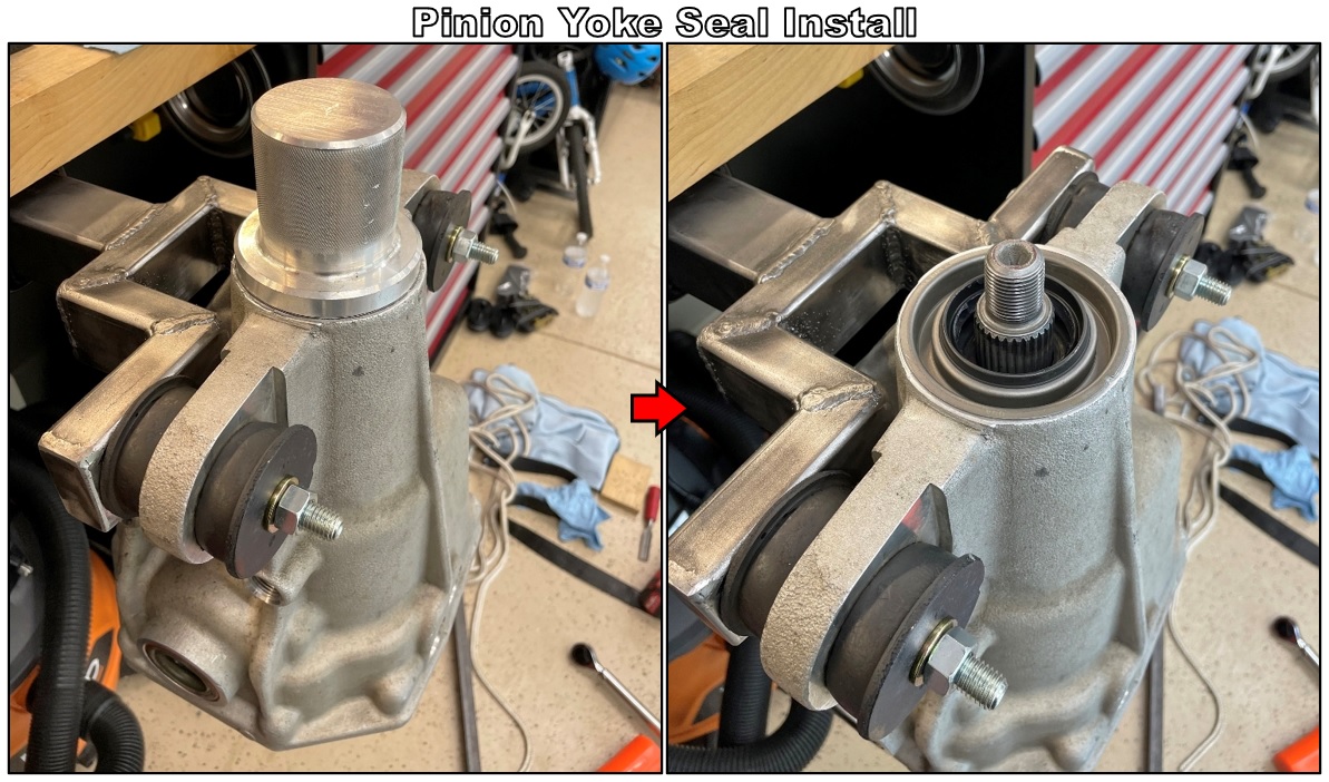
Step 6. Tighten pinion nut to spec while measuring pinion bearing preload
Slide the pinion yoke on. I recommend adding a small amount of Teflon sealant to the pinion yoke splines before sliding it on to keep any oil from seeping past. If you do this, only apply sealant to the yoke splines – otherwise, you’ll drive sealant into the outer pinion bearing as the yoke slides down the splines.
Install a new washer and new pinion nut. I did not use Loctite on the pinion nut. In hindsight, it wouldn’t have been a bad idea. If that nut backs off at all, you’ll lose your pinion bearing preload, and bad things will happen.
Tighten the pinion nut in the same increments you used in Step 3 above and take note of the preload at each increment. The pinion yoke seal will add about +3 in-lbs to your readings, so keep that in mind. The pinion nut final torque spec is 220-280 ft-lbs. I tightened mine to 250 ft-lbs, and ended up at around 30 in-lbs of total preload (27 in-lbs bearings + 3 in-lbs for the seal). I recommend painting a torque stripe on the pinion nut and yoke to allow for quick and easy inspection during routine maintenance.
If you hear or feel any scraping as you rotate the yoke, it is likely the yoke dust shield making contact with the seal. To fix this, you can take a brass hammer and give the dust shield a few taps under the outer edge to bend it away from the seal. The dust shield is pretty thin, and can get bent during the gear pattern checking process.
If you are using a crush sleeve, I wish you luck. Again, preload comes on fast, so tighten with care. If you overtighten the crush sleeve, you’ll have to pull everything apart and try again with a new crush sleeve. Not the end of the world, but still a PITA.
Step 7. Install carrier and tighten bolts to spec
Set the carrier bearing shims in place in the housing. Install the fully assembled carrier + carrier bearing cups in the housing, firmly seating all parts with a dead blow hammer. As always, oil the bearings and all mating surfaces prior to assembly.
Install the carrier bearing caps, double-checking the orientation of each. Install the carrier bearing cap bolts (takes a 19 mm 6-point socket) and tighten to 65 ft-lbs.
Step 8. Measure carrier bearing preload
Flip the housing back over, and measure the total bearing preload. The carrier bearing preload should add approximately 6-10 in-lbs of torque to rotate. Mine added about 6-7 in-lbs. When multiplied by the gear ratio, that fell within the 15-35 in-lbs preload spec for new bearings, albeit on the lower end of that scale.
If there’s too much (or not enough) carrier bearing preload, you’ll have to adjust the shims to bring it into spec. As a sanity check, properly preloaded carrier bearings should require a few good whacks from a dead blow hammer to seat the carrier in the housing. Keep in mind that any changes to the carrier shims will affect your backlash measurements. If you add or take away shim thickness, make sure it is the same amount on each side to minimize the impact on backlash.
Step 9. Measure final backlash
This will be your first sanity check that everything is where it should be. I took 10 different backlash measurements at 10 different locations around the ring gear. Most measurements were 0.005”, with one being 0.0045”, and one being 0.006”. All backlash measurements must fall within spec before moving on to the next step.
Step 10. Final gear pattern check
This is it – the most stressful gear pattern you’ll ever run. If the backlash is in spec, there’s a good chance the pinion depth has not changed, and the gear pattern will be pretty much identical to what you ran before starting the final assembly process. My results:
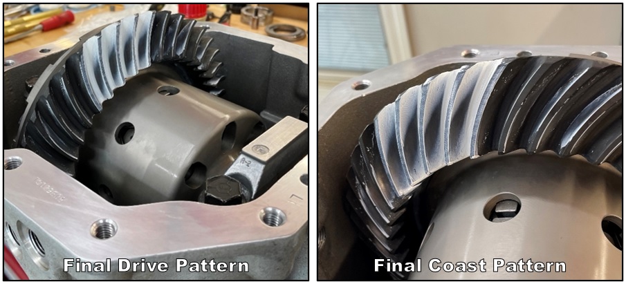
Stick a fork in it – that shit is done. The paint can stay on the gears – it will get washed off by the gear oil during break-in and removed during the first oil change.
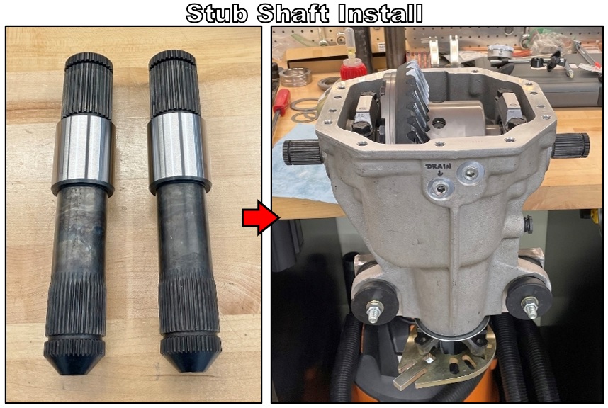
Step 11. Install stub shafts
Drive the stubs in with a dead blow hammer until the internal snap rings click:
Step 12. Install drain plugs
Install all 4 drain plugs with Teflon sealant:
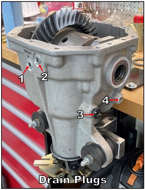
Step 13. Add oil (optional)
You can skip this step until you get the differential back in the car; dealer’s choice. I opted to do it now because of the easy access. Filling the differential with oil while it is suspended from the work bench in this orientation ensures that the pinion bearings are well lubricated before your first drive. As a reminder, the outer pinion bearing only gets lubricated after the oil gets slung up and over by the ring gear, so giving it a little head start isn’t a bad idea.
I added 1.5L of gear oil to the housing – that should get you close to the proper fill level for a newly built (i.e. dry) differential.
Step 14. Apply RTV sealant
Clean the sealing surfaces of the differential housing and cover with brake cleaner. Apply a 1/8” – 3/16” thick bead of sealant around all holes with a bead connecting all of the holes together:
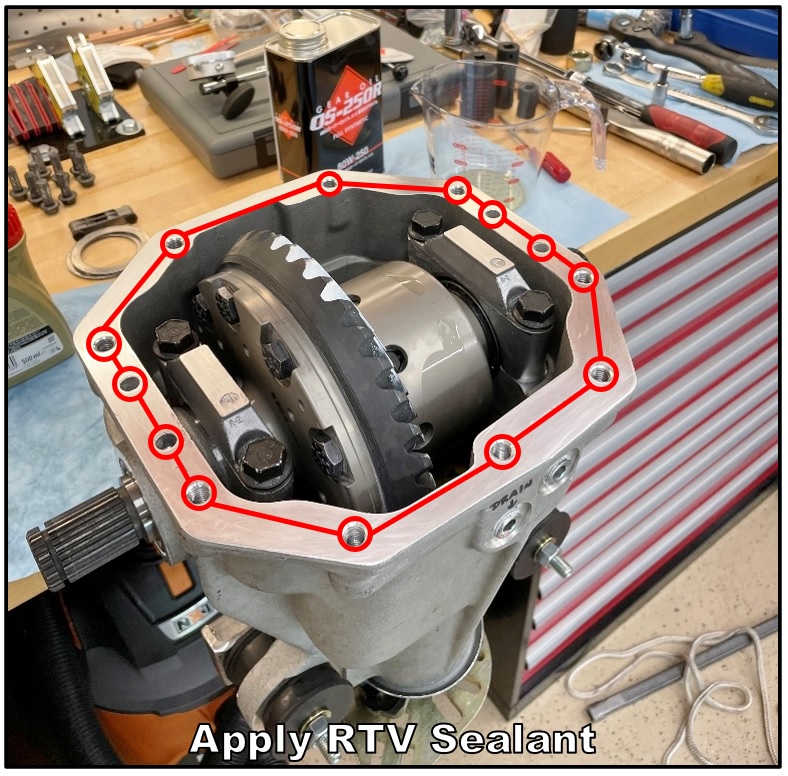
You’ll have about 10-15 minutes of working time (depending on the conditions) before the sealant starts to set. If it starts to set before you can get the cover in place, scrape it all off and start over. The master install kit that came with my new ring and pinion included Permatex Ultra Grey, so I used that.
IMPORTANT: You must apply sealant to the carrier bearing cap supports in the differential cover. This will bridge the gap between the supports and the carrier bearing caps.
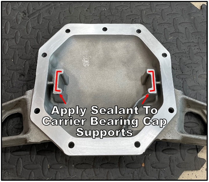
Note: If you did not add oil in Step 13, allow 24 hours for the sealant to dry before adding oil (as per Permatex’s instructions).
Step 15. Install Cover
Carefully place the cover on the differential housing. Install 9 differential cover bolts finger-tight. Tighten bolts in a criss-cross pattern to 35 ft-lbs. The bolt heads require a 13 mm 6-point socket.
Tip: I bought a couple of double-ended M10 x 1.5 threaded studs (https://belmetric.com/m10-double-end...sku=S10X70DYLW) to act as alignment dowels for this step. Once the cover is on and held in place by a few hand-tightened bolts, you can take the studs out and replace them with the proper bolts. This method will prevent the cover from moving around during the tightening process, ensuring the RTV sealant makes a good, continuous bond. If you move the cover around too much, you may end up with a leak path. If that happens, you’ll be pulling the entire differential from the car to try again, so getting it right the first time is essential.
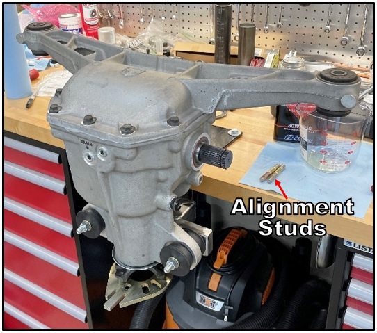
Time to take a little breather – the hard work is done, but there’s still some heavy lifting required to get everything back in the car. I’m not going to provide a step-by-step on how to do that part, as that’s been covered at length in other threads on this and other forums. If you have any questions, though, just ask.
-
12-26-2022 #45Enthusiast


- Join Date
- Oct 2013
- Location
- Dayton, OH
- Posts
- 4,803
An exercise in restraint
Break-In
I finished rebuilding this differential on September 11th. I didn’t get to go for the first drive until October 4th.
The reason? A poorly machined Driveshaft Shop (DSS) heavy duty axle flange.
Story time: In order to remove the differential from the car, you have to pop the axle flanges off of the differential output stubs. The axle flanges are retained by circlips on the stubs. The circlips are compressed during the process of sliding the axle flanges in place; once they are at the proper depth, the circlips spring back into grooves machined into the female splines of the axle flanges, effectively locking the axles in place on the inboard side. In order to remove them, the circlips must release, but that requires the proper machine work on the flange’s female splines – otherwise, the circlips won’t compress, and if they won’t compress, they won’t release. One of my DSS axle flanges refused to release, and it took one of my OEM stubs hostage in the process. Unfortunately, this is not the first time this has happened to me: https://driveviper.com/forums/thread...l=1#post324179
Thankfully, you can just unbolt the DSS axles from the flanges. This design allows you to still be able to get the differential out, but I also needed to be able to remove the stuck flange from the stub. The OS Giken uses completely different stubs compared to stock, and you can’t use the DSS axles without both flanges (the other one came off easily enough).
The removal process didn’t work out so well. I beat on the offending flange for hours with a slide hammer and my custom steel adapter plate to no avail. I finally ended up putting the assembly in my bench vise and gave the stub shaft a few gentle nudges with a punch and a sledgehammer. That resulted in this:
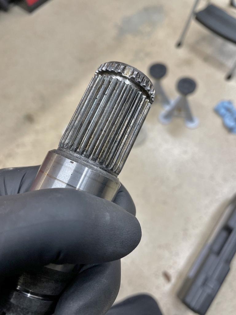
It finally released, but it also knocked the tooth right off the stub and shattered the circlip in the process. I’ll let you do the math on how much force is required to do that. My wife is probably better suited to describe how much of a racket it makes; she certainly notified me within about 30 seconds of the first blow.
It wasn’t the end of the world since I didn’t wake the kids and I also didn’t need to reuse the stub, but my hammering unfortunately messed up the splines of the billet steel DSS axle flange in the process:
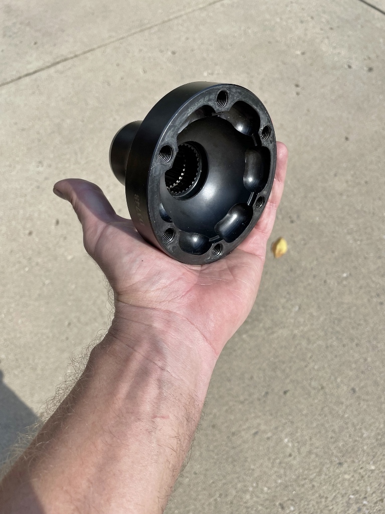
I called DSS, and they were reasonably helpful, but it took way longer than I anticipated to order and receive a replacement flange. It took them a week to get me a quote, several more hours for them to send me a link so I could pay for the damn thing (~$400 shipped), and then I waited a little over 2 weeks before they were finally able to ship one out.
Once I had it in hand, though, I had the car back on the ground and ready to drive in about 2 hours.
The differential’s maiden voyage was to my local gas station:
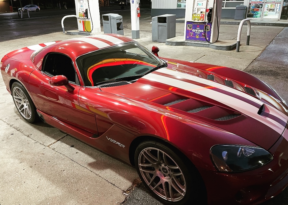
The gears were dead silent. All of my hard work finally paid off.
The break-in process
There are many theories on the proper break-in procedure for a new differential floating around on the internet – if you have a few fingers and access to the Googles, you can read them all at your leisure. I certainly did. There were a few recurring themes, but most of the articles were geared toward large trucks with an intended use of off-roading or towing. For drag racing, some suggested you could just take it straight out to the strip and give it the beans. Here’s the important part for any vehicle that’s going to live its life more than a quarter mile at a time though: break-in is an exercise in heat management. New bearings and new gears are tight, and they’ll both generate a lot of heat, especially on the first few drives. Excessive heat breaks down gear oil; if the gear oil breaks down, the gears and bearings won’t be properly protected, and you’ll either burn up the bearings or trash the gears, possibly both. Either manage the heat, or the heat will manage you and all of your hard work. Here’s the process I followed to keep the heat in check:
1. I drove around for 15 miles at a time for the first 3 drives at no higher than 45 MPH – it was all in-town stop-and-go driving. At the end of each drive, I let the differential cool for at least 12 hours. Overly conservative, but I wasn’t taking any chances.
2. For the next ~450 miles, I did a mix of in-town and highway driving, usually around 50 miles or so at a time. After each drive, I let the differential cool at least 6-8 hours before going on the next one.
I was trying to make at least one trip to the drag strip before my local track closed for the year (end of October), so time was ticking. I took a lot of 5 AM and late-night drives spread out over a couple of weeks to finish up the break-in process:
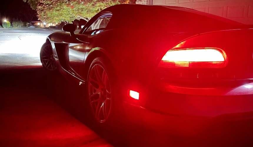
Once you have about 500 miles on the clock, drain the differential and refill with new gear oil. The gear oil that came out was pretty nasty, but that’s to be expected since it mixed with the gear marking compound.
After the oil has been changed, you’re ready to let ‘er rip tater chip!Last edited by Steve M; 12-26-2022 at 10:16 PM.
-
12-27-2022 #46Enthusiast


- Join Date
- Oct 2013
- Location
- Dayton, OH
- Posts
- 4,803
All aboard the fail boat part 2
OS Giken Notes
I have mixed feelings on the OS Giken limited slip differential. On the one hand, the center section itself is made out of billet steel (OEM is cast), and is beautifully machined:

I felt kinda bad knowing it would be hidden in an ugly differential housing. It also had some serious heft to it – it weighed 2 full pounds more than the OEM GKN Visco-Lok that it replaced (25 pounds for the OS Giken vs. 23 pounds for the GKN). It just felt like a nice, solid, durable part that would withstand some serious abuse.
Unfortunately, I can’t say the same for the stubs – if you missed that one, the details are here: https://driveviper.com/forums/thread...-Giken-FAILURE
I’m still not sure why they made parts of the stubs so much thinner in places than the OEM pieces:
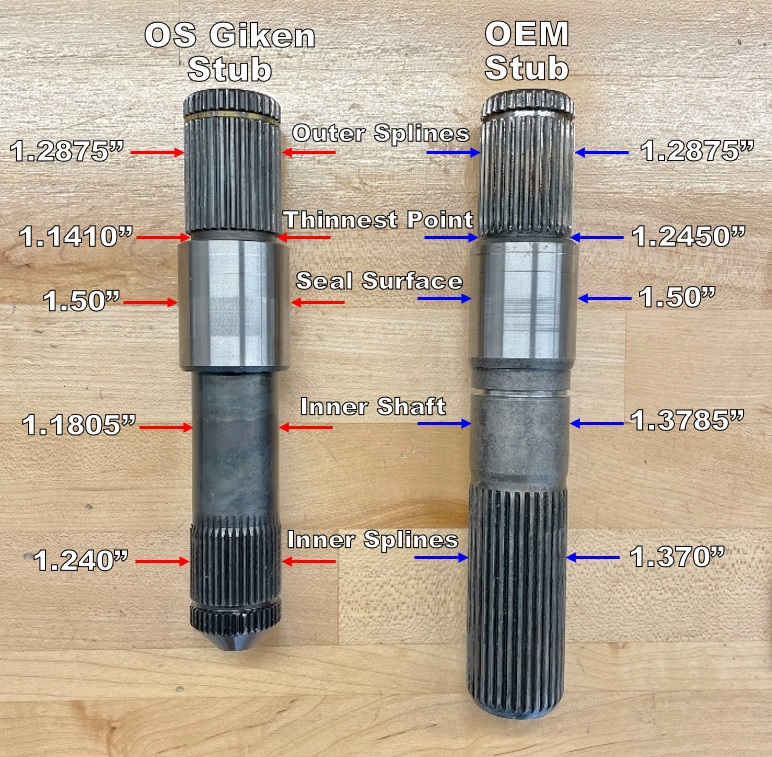
It was no surprise that one of mine broke at its thinnest point where they machined in a nice stress-riser:
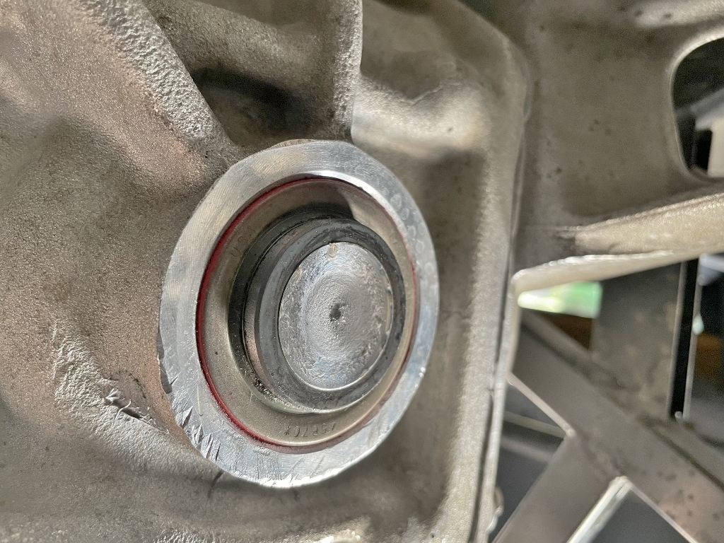
Was it just bad luck? I have no idea, but I don’t intend to invest any more time and money into figuring out what went wrong. It is a piss poor design, unless their intent was to make it a fusible link. If that was the case, then mission accomplished.
The first question that came up after the unit failed was “Did you use the correct oil?”
Hell yes I did – this stuff:

I bought OS Giken’s recommended OS-250R 80W250 gear oil, and that shit wasn’t cheap: $140 for 3 liters shipped to my house (enough for break-in + one oil change).
As is typical with gear oil, it smells like shit, but man did that stuff stick to the gears. It also had the friction modifier required to keep the clutches in the OS Giken happy. I was hoping that the OS-250R would eliminate any popping around tight corners (a common OS Giken issue), but alas, it did not.
I could make tight, slow turns around a parking lot or my driveway with no issues. I could also make long sweeping turns at speed with no issues. Where I had the biggest issue was with mid-speed (like 10-20 MPH) 90-degree turns, like turning on to a side road while driving around town. Those would usually net a pretty good “pop” that would cause the car to shimmy a bit. Unsettling is a good description – it got to the point that I cringed going around pretty much any corner in anticipation of the “pop”, and I’d say it happened about 50% of the time depending on how fast I took a corner.
I did many parking lot Figure-8 sessions during break-in to try and help wear in the clutches – this did help some, although the clutches would get pretty loaded up during this process and give a good POP as I was straightening the car out, likely from the heat generated by the multiple Figure-8s. Oddly enough, I never had a single pop during my one trip to the drag strip, either on the way there or pulling up to the line. The GKN Visco Lok would usually make at least some noise when pulling around and backing in to the water box for my burn out, but the OS Giken didn’t. At least not for the one run I got out of it. A single data point does not a trend make, however.
Would I recommend the OS Giken for a car that spends any amount of time on the street?
No. It makes a fair amount of racket going around high-speed turns (e.g. long sweepers on the highway), probably best described as a combination of light grinding and whirring. The random popping around corners, though, is what makes it not street friendly in my mind. I never lost control, but it definitely makes you pucker up a bit when it happens. I always worried it would happen on a highway on/off ramp, but thankfully it never did. That would have been disastrous.
Would I recommend it for a track car?
Maybe. Certainly not for drag racing, but that’s purely due to the poorly machined stubs. If they would fix that one issue, it would probably be just fine. If anyone knows a contact at OS Giken that can actually get shit done, feel free to pass along my contact info, and I’d be happy to help them fix it. Their US Distributor was worthless, though. At this point I’d highly doubt they give two shits about a limited production car like a Viper.
Meh…live and learn I guess, but that was one very expensive lesson.



 Reply With Quote


Bookmarks