


For those that have been following the Gen 5 development, you are aware that SRT switched to a composite intake manifold with slightly longer runners and better airflow characteristics. This new intake makes up the bulk of the gains in power/torque over the outgoing Gen 4 car. I'll outline below the process to install a gen 5 intake on a Gen 4 Viper with some pics for reference.
The first thing you need to do to the Gen 5 intake is remove the torque limiters from the intake. They are aluminum dowels with a plastic bolt locator inside that are a slight interference fit in the intake bolt holes. The purpose on the Gen 5 intake is to function to limit torque applied to the manifold itself by bottoming out in a receiver groove machined in the Gen 5 cylinder head and also to center the intake over the head intake ports. You can see them just barely peeking out the bottom of the intake bolt flange here.
Because the Gen 4 doesn't have these receiver grooves machined into the head, you need to cut them down so that they don't protrude from the bottom or top of the intake while still keeping the plastic bolt locator inside. I used a punch and small hammer to push them out...they come out easily.
In the pic below, you can see the overall length is about 5mm too long. I measured each of the flange holes and found that none of them are shallower than 27.5mm deep.
I decided to cut all of my dowels to a length of 27mm so I'd have a cumulative clearance of 0.5mm or more between the intake flange top and bottom and the ends of the dowels. There are a couple ways of doing this. Some folks cut them at an angle but I elected not to do this. The reason why is because if you were to inadvertantly have one of the dowels rotate in the intake flange hole, it would become and interference fit with the intake to the head and not let the intake seat fully down. Here they are cut to length and cleaned up.
As a quick aside, in this picture you can see I mounted the bolt locators on the bolts as they are easily removed from the dowels and also elected to place a single stainless washer under the head of the bolts that was 0.625" in diameter - just slightly larger than the bolt to prevent galling of the intake when tightening them down as well as to give a little more distribution of torque over the relatively soft composite intake (more on this later!).
Here you can see a couple of the dowels installed and the clearance between them and the intake flange bottom. The tops of the dowels were all flush with the top of the intake flange.
Now comes the actual start of the project! Pulling the intake is a relatively simple procedure. Just unplug the master cylinder vacuum source and sensor from the rear of the intake, remove the airbox, unplug the MAF sensors and TB plugs and a few vacuum lines attached.
After you do that, you are left with this. As you can see I don't have a catch can installed (but will soon!) and the resultant oil present in the intake manifold and dripping off the TB's. Everyone needs a catch can on these cars. I cleaned off the head mating surface to the intake with alcohol so that no oil would remain and I would get a good seal with the new o-rings on the Gen 5 intake prior to placing it on the motor.
Next I removed the vacuum lines that "T" together under the stock manifold that I removed and attached them to the underside of the Gen 5 intake. They don't have hose clamps from the factory but I installed clamps or zip ties on all connections just to ensure I don't have any vacuum leaks (Thanks for the rec Flatout!).
In the next pic, you can see that just behind the "T" hose, that I have a rubber 90 degree elbow and reused the plastic hardline that went from the PCV on the passenger valvecover to the stock intake because I plan to run my catch can in the factory recirculated fashion. I won't go into all the technical details as to why but I believe I have a valid reason and the benefits outweigh the drawbacks. There are those that run an open catch can vented to atmosphere from the crankcase. If that is the case, you just need a vacuum cap and clamp to cover this hose fitting on the underside of the intake.
TB's are bolted back on. I made sure to keep the driver side TB on the driver side of the new intake and vice versa. Wasn't sure it was absolutely necessary but since I didn't install the Mopar PCM yet, I didn't want to upset the factory computer any more than I was doing with the new intake.
Here's a pic side by side for comparison FWIW (not much).
Now the tedious process of torquing this thing down. 20 bolts and stepwise torquing is painful (in your back) after you've been hunched over walking around the car multiple times.
I numbered the torque sequence on the handy-dandy plastic thing that came on the intake to keep myself straight. I also torqued the intake down incrementally in the following order - just snug, 40 in-lbs, 60 in-lbs, 90 in-lbs.
Got everything buttoned up and then took her for a test spin.

Results 1 to 25 of 37
Hybrid View
-
03-23-2014 #1Enthusiast


- Join Date
- Nov 2013
- Location
- Indianapolis
- Posts
- 1,256
Gen 5 Intake Install on Gen 4 Viper
Last edited by IndyRon; 03-23-2014 at 09:48 PM.
-
03-23-2014 #2Enthusiast

- Join Date
- Oct 2013
- Location
- Montgomery Texas
- Posts
- 6,732
Looks great and awesome garage space to wrench. I'll throw in my two cents once you upload the rest of the install.
-
03-23-2014 #3Enthusiast
- Join Date
- Nov 2013
- Location
- Indianapolis
- Posts
- 1,256
As an addendum, after taking the car out, it drove great! No check engine lights. No hesitation. The car makes gobs of power already but there was a large improvement in torque between 2500rpm and 5000rpm as well as a perceived increase from 5000rpm to 6000rpm as well. After cruising for 20 minutes at various RPM's and load conditions in different gears and a few WOT passes, I brought the car home, parked it and let it cool down overnight.
I went back and retorqued the intake manifold the next day. I found that most bolts required another 3/4 to 1 full turn to reach torque spec. I have some concerns about this. It doesn't appear that the bolts have loosened but rather the intake has compressed some from the torque, heat cycling, and fatigue. If you look in the pic below, you can barely see (it's hard to make out) that even the larger washer is digging into the medial (right) aspect of the flange.

I'm contemplating going to even larger washer as one possible alternative. I also think that 95 in-lbs may be a little on the heavy side for torque. I torqued mine to 90 in-lbs and think even that may be a little high for this material. Here is my rationale. The Gen 5 receiver groove allows the dowel to bottom out with just enough compression on the rubber o-ring gasket to seal the intake and the additional torque is transferred to the cylinder head via the dowel and not directly on the intake manifold like it is in the Gen 4 install. The actual torque on the intake and the o-ring is then a function of the amount of compression of the o-ring which we know is not complete otherwise the dowel would not bottom out, the intake would bottom out on the head in the Gen 5. There is no gap between the intake and head on the Gen 4 install, therefore the o-ring gasket is as compressed as possible and likely more compressed than the Gen 5 is. I placed a wite-out mark on the bolt and intake to confirm that the bolts aren't backing out and will follow this to confirm but I don't think they are. I plan to retorque the intake a few more times and this next time I am only torquing it to 80 in-lbs and I believe that will be sufficient. This is just my plan, if you want to do differently I understand. But keep in mind, the intake was not designed to be installed and used as the primary surface to determine torque values so I am just going to be cautious. I plan to have it back at the dyno in a week or so to get some follow up numbers once I have my catch can installed.Last edited by IndyRon; 03-23-2014 at 09:45 PM.
-
03-23-2014 #4Enthusiast
- Join Date
- Oct 2013
- Location
- Montgomery Texas
- Posts
- 6,732
Yes go to a slightly larger washer. Also as noted in the original install thread many of us had to retorqued a few times and the intake seems to eventually "settle" and retain the torque specks. Also just checking but did you buy the 2013 PCV line? I see the blue check valve with no hose on the end of it. Did you just leave this uncapped prior to the catch can install?
-
03-23-2014 #5Enthusiast
- Join Date
- Nov 2013
- Location
- Lucas, Texas
- Posts
- 2,009
Great write up and good documentation.
I re-torqued mine after one full heat cycle and had the same results you did on the second tightening. I have NOT re-torqued those again and the intake has about 600 trouble free miles on it now. I see no reason to continually re-torque these if you are not having issues. I did however trim my torque limiters at an angle.
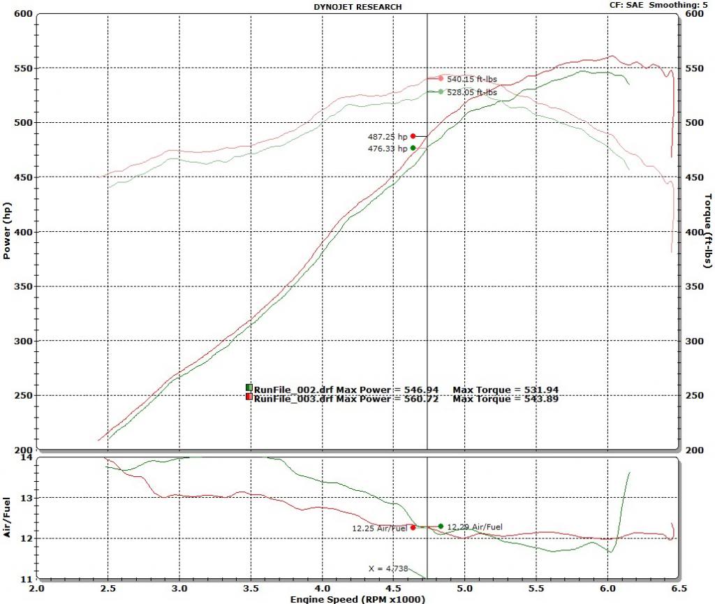
These are before and after dyno runs on 08 with ONLY the intake change. I do have a Mopar PCM. I am looking forward to seeing your numbers as well.

-
03-24-2014 #6Enthusiast
- Join Date
- Nov 2013
- Location
- Indianapolis
- Posts
- 1,256
Andy, I didn't need the 2013 PCV line as I used the OE hardline that runs from the passenger valve cover in front of cylinder 2 to the stock intake and then bought a 5/8" 90 degree rubber elbow from auto zone. For the test drive, I just capped the pcv as well as the vacuum line going under the front of the intake. Since I had the driver side PCV vent that plugs into the airbox between the MAF sensors hooked up, I had a vent for the crankcase. It's not optimal nor the way the system was designed to work, but is sufficient for just the test drive until I get my catch can this week.
Frgmstr, I'm sure the angled cuts on the dowels would and are working just fine too. I just didn't want to chance it even if it were a remote possibility of causing a problem. Thanks for posting the dyno numbers on your setup. I am curious, you had good gains from the switch - 18rwhp peak, but I was thinking in other dynos, the intake was worth 25-30rwtq in the midrange. in your runs, it seems to be pretty linear at approx. 12-18rwtq increase throughout. What other upgrades do you have done to hit 608?Last edited by IndyRon; 03-24-2014 at 01:01 AM.
-
03-24-2014 #7Enthusiast
- Join Date
- Nov 2013
- Location
- Lucas, Texas
- Posts
- 2,009
Belanger headers, cat delete, Corsa catbacks, Gen V intake, and Mopar PCM is all. Originally Posted by IndyRon

My 08 Vert was built for a long time Dodge dealership owner in Minnesota. FWIW, I have always felt that it might have gotten a "special" motor in it given the stocker RWHP numbers that it put down. Certainly stock HP numbers were not near the low end.
-
02-13-2020 #8Enthusiast
- Join Date
- Jan 2017
- Posts
- 155
How long did the install take? Originally Posted by IndyRon
-
03-24-2014 #9Enthusiast
- Join Date
- Oct 2013
- Location
- Ontario,MCVO,PA,OH
- Posts
- 2,671
Great info ! Thanks for sharing !

-
03-24-2014 #10Enthusiast
- Join Date
- Nov 2013
- Posts
- 461
Great write up Ron I'm curious as to what we can get out of a ported Gen 4 in comparison! Either way well thought out write up.
-
03-25-2014 #11Enthusiast
- Join Date
- Nov 2013
- Location
- Lucas, Texas
- Posts
- 2,009
Originally Posted by Revolution
I was just about to send my Gen IV intake out to BBG to be ported when I started seeing this Gen V intake mod. My research showed the Gen IV ported heads averaging around 20HP or so. Considering this mod costs less than having the stocker intake ported, I figured it was worth a shot and now I have my stock intake to put back on the car when/if I decide to sell it. Would likely save a $1000 later, or surely I could sell it off for an easy $600 or so.
-
09-23-2014 #12Enthusiast
- Join Date
- Sep 2014
- Location
- Allen TX
- Posts
- 306
FYI to all: The intake is compression molded unfilled PPA material, compressive yield strength is 10ksi.
also, PPA is hygroscopic, which means it absorbs fluids (water). when this happens, the mechanical properties of the manifold (compression/tensile/yield/elognation/wear/etc) drop to about 35% of their original strengths, at 90 F. keep it dry. everyone has different washers/screws setup, I ordered new ones from MSC Direct....
Bolts: 83243014
Washers: 742137375
my washers OD are 16mm, which runs just about cordial/concentric with the plastic flanges.Last edited by jvm728; 09-23-2014 at 01:31 PM.
-
09-23-2014 #13Enthusiast
- Join Date
- Oct 2013
- Location
- Montgomery Texas
- Posts
- 6,732
Also an update on this mod from Dick Winkles himself. I disucssed this install with him and the torque limiters. He did mention that the torque limiters were also necessary to keep the plastic from cracking. I spoke to him about the larger washer to help distribute the clamping force which he thought made sense. Also the most important thing he said was that the gaskets were evenly compressed. So if you're not having any leaks than you are in good shape. If you are still experiencing some of these symptoms than add the washers to help distribute the clamping force.
-
09-23-2014 #14Enthusiast
- Join Date
- Nov 2013
- Location
- Indianapolis
- Posts
- 1,256
Good information. I've torqued mine a couple times since the install but have since stopped torquing them to 96 in-lbs and the last time (which was a couple months ago) only torqued to 70 in-lbs to prevent further compression of the flange. I also used a 3/4" OD washer (19mm) under the bolts to also distribute the load. Since the entire manifold head mating flange was still compressed completely against the heads, my rationale was that the rubber o-rings were adequately sealed and didn't need further torquing.
-
10-02-2015 #15Enthusiast
- Join Date
- Oct 2013
- Posts
- 86
Great write up. Made my install a lot easier I am sure!
Thanks
-
10-27-2015 #16Enthusiast
- Join Date
- Apr 2015
- Location
- Plainfield, IL
- Posts
- 419
So I'm in the middle of this swap and was wondering... I don't have the hose going from the original intake to the airbox... so for the opening on the bottom of the Gen5 intake, behind the "T" connector, do I need to just cap that off?
-
10-27-2015 #17Enthusiast
- Join Date
- Nov 2013
- Location
- Lucas, Texas
- Posts
- 2,009
Misread. Originally Posted by Ninjazx71
-
12-12-2015 #18Enthusiast
- Join Date
- Jan 2014
- Posts
- 73
Just picked up my Gen IV Intake and ill be referencing your write up while doing this swap. Is this mod worth it and do you really feel the seat of the pants feel? Also I do not have a PCM, only stock, can I use the stock PCM after doing this? Should I wait on doing the swap and buy the Mopar PCM, or HPtuners PCM? Thoughts from the experts?
Beautiful write up and thank you.
-
06-05-2016 #19Enthusiast
- Join Date
- Jan 2014
- Location
- Townsend TN
- Posts
- 269
In my opinion, and on my car for sure, a positive SOPs difference. The torque was stronger in the midrange, and the engine ran smoother....AND THEN I ADDED THE MOPAR CONTROLLER :-) Awesome. Don't hesitate, just do it. On the other hand, get the parts, but be driving your car for the next month to really get a good feel for 'baseline', THEN CHANGEOVER. You'll have perma-grin. Originally Posted by ViperWally
it would be nice (and i may have missed it!) if someone would show dyno pull charts of before and after by steps - first baseline, then intake, then controller with intake. I'd like to see that.Last edited by TCurtner; 06-05-2016 at 04:01 PM.
-
12-12-2015 #20Enthusiast
- Join Date
- Nov 2013
- Location
- Indianapolis
- Posts
- 1,256
Wally, I have some back to back dyno's of the gen 5 intake with stock PCM somewhere on here then with the Venom PCM. If I remember correctly it picked up with the intake solidly through the midrange but peak numbers were essentially unchanged. It wasn't until I put in the Venom PCM that the peak numbers increased also.
Seat of the pants it IS noticeable. Probably the second most noticeable bolt-on, after headers.
-
01-05-2016 #21Enthusiast
- Join Date
- Jan 2014
- Posts
- 73
Hey Guys the Intake I bought was cracked at the throttle body so I sent it back. QUESTION I have is I found them here http://www.moparpartsoverstock.com/s...sembly=1209578
they have one for 931.48 and 977.88 they have different part numbers Alex said dont worry about it BUT I want to make sure what intake do I get to put on my 08?
Thanks and awsome post im going to use
-
01-05-2016 #22Tech Team
- Join Date
- Oct 2013
- Location
- Port Charlotte, FL
- Posts
- 782
AE is the newest version of the part, AD would be cheaper, *IF* it is still available. It could be an actual change, it could be nothing more than a change in manufacturer or a price change and new number. Either part number will net the "same fitment component".
-
01-05-2016 #23Tech Team
- Join Date
- Oct 2013
- Location
- Santa Monica Ca
- Posts
- 819
Doug Shelby makes a nice manifold installation kit with revised torque limiters.
-
05-30-2016 #24Enthusiast
- Join Date
- Oct 2013
- Location
- Dayton, OH
- Posts
- 4,803
Bumping this back to the top for a quick update since I just tackled my own Gen 5 intake manifold install this past weekend...one thing I wondered about was how to connect my catch can to the Gen 5 intake manifold. The Gen 4 has the port on the passenger side of the manifold facing the outside of the car, but the Gen 5 manifold PCV port is in the center between the two throttle bodies facing down. This requires a 90° bend of some sort in order to clear the wiring harness that runs through this same area once the manifold is installed. Here was my solution:

What you are looking at is a pre-molded 5/8" heater hose, Dayco part number 80405 ($15 from Summit: http://www.summitracing.com/parts/DAC-80405). I have no clue what the original application was for this particular hose, but I saw the nice 90° bend I was looking for and decided to order it so I could cut the part I wanted and toss the rest. Once you cut the part you want/need, you can toss a 5/8" hose barb to -10AN male adapter on the end of it (Jegs part number 555-110583: http://www.jegs.com/i/JEGS-Performan...10583/10002/-1), and voila. Now it's just another serviceable connection.
Here's another picture showing that hose along with the other vacuum lines that T together right in front of it:

Hopefully that helps more than it confuses...I'm sure there might be others out there trying to figure out how to adapt it to their particular application just like I was.
On a side note, now that I have a wideband installed full time on my car, I decided to monitor what just installing this intake manifold did to my air fuel ratio...the high flow cats I added earlier this year (which allowed me to install a full time wideband) leaned the car out pretty substantially (I was commanding 12.6:1 and was getting 13.1-13.3:1), but this intake manifold made everything go rich (I'm still commanding 12.6:1, but am now getting 12.2-12.3:1). This is pretty much what IndyRon found too with the stock PCM (you can read about that here: http://driveviper.com/forums/threads...highlight=dyno). No big deal since I can go back with HPTuners and lean it back out, but I just thought it was interesting that opening up the exhaust leaned things out, and this intake manifold had the opposite effect.
-
06-05-2016 #25Enthusiast
- Join Date
- Oct 2013
- Location
- Dayton, OH
- Posts
- 4,803
From this thread (linked in my post above): http://driveviper.com/forums/threads...highlight=dyno
Blue line was the baseline dyno, red line was adding only the Gen 5 intake manifold:

Then after adding the Mopar PCM and UD pulley:


 Reply With Quote

Bookmarks