
This is a "how to" on a full Belanger exhaust for 2013+ Vipers. This is the catted setup. I would assume that the instructions below would work for American Racing, M&M, and other brands. I am not a technician but have some experience turning a wrench and the confidence to work on my Viper. My best advice is to take your time and make plenty of mental notes! This is not a fast swap. It is simple and it is easy but it is not quick. I completed this over 4 days around 2-3 hours per day.
Tool/parts/item List:
Dodge Viper (duh)
Jack stands and floor jack- or a lift.
1/2" drive ratchet
1/4" driver ratchet
8mm,10mm, 13mm, 16mm, 17mm, 5/8" socket
13mm open ended wrench
Phillips screw driver
Torx number #20 and #27
1" hose clamps (depends how many you want to replace)
Permatex Copper high-temp sensor safe silicone
1. Jack up your Viper with jack stands and remove rear wheels
2. Remove X brace- 13mm socket
3. Remove Valve Cover Covers- just pull upward. There are 4 Rubber grommets that hold the covers in place. The drivers side needs to have the Oil cap removed also.
4. Remove wiper blade arms. Be gentle with the rubber bolt covers. I used a little screw driver to remove the grommets and then side to side upward pressure on the wiper arm to get them loose. 13mm socket
5. Remove wiper cowl. Some of the torx bolts are hard to see. When you remove the cowl be extremely careful of the rubber gasket that goes under the hood. Its held in place by a bunch of these oval plastic clips and if you aren't careful they will break the rubber gasket. (ask me how i know). There is also an 8mm bolt inside the door jamb on each side of the car. Torx #20 and 8mm socket
6. Remove HVAC box. 8mm socket and Torx #20
7. Remove passenger side valve cover. You could remove the coils if you want but i think that is unnecessary. Just unclip the coil plug, pull the spark plug wire from the spark plug, remove the bolts, there are 3 plastic clips that are pressed into the cover, you have to pry these off the valve cover before you remove the valve cover. Don't break them! Then lift the valve cover away from the head. Take note the the oil dipstick tube uses one of the valve cover bolts. Put the valve cover in a clean dry place. 10mm socket
8. Remove passenger side spark plugs. 5/8" socket
9. This next step is probably not 100% necessary but i was advised to do it as a precaution. Remove coolant overflow tank. I had a hell of a time draining the tank and lines without getting coolant everywhere....I used a Gatorade bottle and just filled it up a bunch of times and put the coolant in a larger container. Instead of wrapping the coolant lines with that DEI heat reflective tape, I bought some DEI Titanium heat sleeves for the coolant lines. I like the look better and i am hoping that they perform as well as advertised. I also replaced the hose clamps that had the sleeve with regular adjustable clamps as it was impossible to slide the OEM clamps over the sleeve and the hose. You have to drain every line individually. I also found it a lot easier to put the sleeves on the lines with them completely off the car and dry. This step was the most annoying part of the whole swap. As I mentioned you could be fine with just wrapping the coolant lines and not removing anything. While I was at it I wrapped the wiring for the windshield washer fluid pump with DEI heat tape as it is very near the header.
10. Remove drivers side valve cover. Same process as the passenger except that you do not need to remove the spark plugs (the manifold will come right out- there is more room between the frame and engine on the drivers side). Take note that there is a ground strap on the front of the valve cover that has a nut and bolt. Un-clip coils and set the valve cover in a dry safe place.
11. With the rockers, push-rods and springs exposed to the environment, I covered the whole engine with a towel to prevent debris or junk from falling into the engine. The rockers are a really neat design.
12. Remove passenger side sill. There are a lot of bolts to remove for the sills. I recommend removing the 10mm screws from the underside of the sill first. There are a bunch of them. Maybe 10 screws. Two at the very rear of the sill and then 1 screw every 8 inches or so until you reach the front of the sill.
There are 3 torx #27 bolts in the front wheel well that need to be removed.
In the rear wheel well there are quite a few Torx #27 bit bolts. Remove all the bolts on the rear of the side sill and the wheel well cover. That will include the bolts on the wheel well cover that are bolted to the rear bumper.
Gently pry away the wheel well cover to expose the insides of the cover from the rear. There is a metal bracket inside that has two 10mm nuts that need to be removed. There isn't a lot of room to work and the wheel well cover has sharp edges.
Next remove the 3 screws that hold the Aluminum sill plates.
There is a Phillips head screw on top of the sill that needs to be removed in the door jamb.
Next remove the three 8mm bolts near the washer fluid container. There is also a rubber hood bump stop that needs to be removed and has a #27 Torx bit. Gently pull the side sill off the car being extremely careful not to drop it. You cannot remove it with the door closed and this poses a need for dexterity/agility to remove the sill and not scratch the door or drop the sill. Place the sill in an out of the way place where you wont trip over it or drop anything on it.

Results 1 to 25 of 30
-
10-02-2016 #1Enthusiast


- Join Date
- Apr 2015
- Location
- Silver Springs FL
- Posts
- 2,399
Gen V Belanger Header install photo intensive
Last edited by ViperPete; 10-04-2016 at 08:59 PM.
-
10-02-2016 #2Enthusiast
- Join Date
- Apr 2015
- Location
- Silver Springs FL
- Posts
- 2,399
13. The exact same process is used to remove the drivers side sill.

14. The cat back seemed unusually easy to remove. My car has 10k of miles and there was just a little surface rust which worried me at first but there is literally only 1 clamp you have to remove to get the exhaust off. First un-clip the o2 sensors from the wiring harness and exhaust and put in a safe place. There is a Band Clamp at the manifold/cat back junction. Remove the nut and slide the bolt free. Then take a screwdriver and pry the clamp apart, and completely remove it. Next unbolt the cat-back exhaust hanger. Next unbolt the rear exhaust hanger by the tip. The cat-back will drop so be careful. Voila! You removed the entire cat back with only 1 clamp! Reinstall the rear exhaust hanger bracket. Leave the cat-back bracket off. 13mm socket for the exhaust hanger brackets.


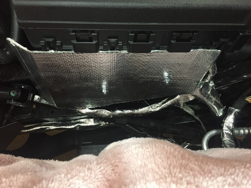
15. Remove the exhaust manifolds. After fighting with the passenger side manifold for about 20 minutes i decided to unbolt the engine from the mounts and raise it up approximately 1" The nuts are 17mm, one for each mount. Some people have been able to remove the manifold without raising the engine but my car was too tight. The drivers side came right out without raising the engine. Once the manifolds are removed, reinstall the engine mount nuts.
You can see the engine mount and the nut removed.

16. The Headers came with some sleeves for the o2 sensor wiring and also o2 sensor extensions for the rear 02 sensors. I wrapped all the o2 sensor wiring with DEI heat tape and also used the heat sleeves that came with the headers. For the o2 sensor extensions that were already sleeved, i just wrapped over the sleeves with DEI heat tape.


17. I purchased the ECU heat shield from Woodhouse. Nice piece of steel. Installation was simple but i found that there was no way to install it without putting the bolts through the back side of the shield and the nuts then on the outside. Even with unbolting the ECU from the car and having some more wiggle room, my hands were too big. Still came out fine. While i was in the area i wrapped the brake lines that were near the header area and also some wiring that was near.


What a difference in design!


18. The header instructions called for reusing the stock header bolts but came with new 8.8 grade SS bolts, washers and lock washers, so i used those. They are 13mm. The headers are actually 3 piece. I found it easier to get the headers into place by installing the rear 2 primary header first then getting the 3 primary header in place. You will have to gently twist and tilt the header to get them into the right location. I also opted for the 3 ply metal OEM replacement gaskets instead of the cloth ones. The stock ones would have probably been reused....oh well. Bolt in the headers only finger tight. Don't they look pretty?

19. The header instructions also call for some Permatex silicon to be used on the lower header joint as well as the collector side for the cat back. Apply a 1/4" or less bead all the way around. This part can be pretty messy. Once the have the lower header part lined up, get a bolt and nut started. Then start the other 3. There is not much room to work and you're going to get silicone all over your hands and the collector so have paper towels handy. Tighten the bolts. Do this on bolt sides. I used a combination of 17/16mm sockets and open ended wrenches. The nuts are a locking type and don't go on easily.


20. Install cat-back. It helps to have another person for this part. You need to line up the cat-back with the collector. If you don't have a helper you can use some boxes to get the cat-back into place. The cat-back is secured with 3 bolts. The collector also has to have Permatex silicone applied. These bolts are a pain. The nuts are a locking type and don't go on easily. There also is not much room to get to the top bolt. Take your time.
Before I installed the cat-back I taped this DEI shield to the cat back. Its about 24" long and covers the top half of the exhaust. I used some metal zip ties to secure it and seems to work great! I didn't want to wrap it with the exhaust wrap as the instructions warn that that will destroy the coating and void the Belanger warranty.

21. Tighten the header bolts. They are 13mm and I used a socket for some and an open ended wrench for others that are a bit tight.
22. Now you need to route the o2 sensor wiring. First start with the rear passenger side o2 sensor. Once the extension is fully wrapped, loosely screw it into the cat-back. Then take the wire and go up and over the heat shield. Remove the 8mm bolt that holds the side valence and slide the wiring under and behind it. snake the wiring around the HVAC box. I taped the wiring to the firewall to make sure that it would not move as there is only about 2-3" of clearance from the wiring to the rear primary. There are 2 o2 sensor wiring clips that you have to remove so that there is enough wire to keep the wiring away from the header. I wish i had better pictures to illustrate this. Once you are under the car you will see what I am talking about. The front o2 sensor is straight forward. Try and keep it away from the primaries.


23. The drivers side is easier. Do the same thing for the rear o2 sensor. Now as you snake it under the brake booster unbolt the heat shield that is near the starter. Snake the 02 sensor wire behind that heat shield and then reinstall. Then proceed to clip the wire behind the starter. The front o2 sensor wire is to be installed like the passenger side. Do your best to keep the wiring away from the primaries. You can tape the wring to the firewall/underside as an extra precaution.


24. The rear tips will now need to be adjusted and clamped. First you must install the side sill into a rough position so you can figure out where the tip needs to be. I had a hell of a time getting the tips onto the exhaust hanger. I ended up using a rubber mallet and gently encouraging the tip into place.Once you have determined where the tip needs to be, remove the side sill and tighten the clamps. Do this for both sides of the car. 15mm socket
25. Reinstall the side sills. I found that bending the factory metal heat shield over the cat-back a bit makes it easier to install the side sills.
26. Reinstall valve covers. Tighten the bolts in a criss-cross fashion. DO not over tighten!
27. Reinstall coil clips and spark plug wires
28. Reinstall coolant lines and coolant over flow tank. Refill tank with coolant. Zip tie the coolant lines as far away from the headers as you can.
29. Reinstall HVAC box.
30. Reinstall wiper cowl and wiper blades.
31. Reinstall Viper valve cover covers
32. Reinstall X brace
33. Reinstall rear wheels
34. Lower Viper to the ground.
35. Reconnect battery
36. Start car and let warm up. Check for coolant leaks. Go for a drive. The smell of the exhaust curing is pretty powerful. I went for around an hour drive and the smell got worse and worse. I let the car sit in the garage over night and the smell was completely gone in the morning. My car has had no CEL and i've put around 50 miles on it. Drives incredibly well. The sound is great, loud and deep. There is a very noticeable power increase from 2k-5500 rpm. A huge difference.
I have a vibration on both sides of the car and i suspect that it from the exhaust tip clamp coming into contact with the car. I am going to remove the side sills and adjust this. Other wise no issues so far.
Good luck and feel free to ask questions.
EDIT:
Jack B's 2 cents on installing ARH Headers. The install is extremely similar but with some differences.
The Belanger install and the ARH install are virtually identical with the exception on how you handle the five-into-five flange. For either install, here are the major elements:
Muffler Tip:
Remove both mufflers, prior to removing the mufflers, mark the frame with a permanent marking that denotes the beginning of the muffler input, this allows you to estimate the required length of the turn out/j-pipe. When reinstalling the muffler, for positioning purposes, the bottom of the exhaust outlet in the sill is approximately 1-9/16” above the bottom of the frame rail/underside.
It is critical that you start the header gasket locator bolt first. There is one tight fitting hole in the header gasket, it is in the center tube. If you do not start it first, you probably will not be able to get it started. Start all the header bolts by hand and tighten the first few turns by hand.
Bolt the headers in place and torque to 21 ft lbs.
The ARH headers are asymmetrical, there is a left and right side, be care you can get them mixed and they will install on the wrong side.
The lower half of the header is also asymmetrical, there is a left and right side, the O2 bung is at the front of the car that tells you which is the right or left side.
Connecting the Upper and Lower Header Sections (Flanges)
This is where the fun starts, to this point the ARH headers are easier to install than the Belanger’s. Two things make the flange bolts difficult to install, starting the bolts and torquing the bolts. The tubes interfere with the wrench. To make more clearance, I changed out the ARH bolts (3/8 X 16 hex bolt) to a 5/16 head 12 point bolt (1” length), this gives the wrench more clearance. Note, either a 5/16 or 8mm socket/box wrench can be used on a 5/16 bolt head.
To make it easier I used a skim coat of high temp red to attach the gasket to the lower flange, make sure it has dried.
Drivers Side:
On the driver’s side you must remove the starter to start and tighten the rear flange bolt.
On the driver’s side you must peel back the rear half of the wheelwell liner (next to the frame) to start and tighten the front flange bolt. This requires removing the fasteners on the back half of the wheelwell liner. You will have to pull the liner towards the outside of the car and start/tighten with your hand through the opening you just made.
Two bolts are started from the top side with the claw tool in the picture below.These two are then tightened with the 1/4" drive/5/16 swivel socket and long extension. You can use a 3/8" drive ratchet, but, you still need to use the 1/4" drive socket and extension due to space limitation on the flange.
The last two bolts are started and tightened from the bottom side. Keep in mind you will need the 2" long wrench to start these and the longer box wrench to do the final tightening.
Passenger Side
On the passenger side you must peel back the rear half of the rear wheelwell liner (next to the frame) (to gain access to the front flange bolt. This is the same as the procedure on the drivers side.
The remaining bolts are done just like the drivers side.
When I mentioned the “right tools”, refer to the picture below. I cut a 5/16/12 pt wrench down to two inches and then ground the wrench head to give it more clearance, this is because of the interference from the tubes.
More Detail on the Flange Bolt Portion (sort of a repeat)
There are two bolts on each side that can be started and tightened from the top, these should be started first. You will have to use a ¼” drive socket and a ¼” drive swivel socket. The ¼” extension must be a minimum of 24’ long. Also keep in mind, I used 12 pt x 5/16 head bolts. To start these four top bolts (two per side) I used a claw type grabbing tool to hold the bolts for seating prior to tightening with the ¼” drive sockets.
For the four bolts (per side) that are accessed on the underside of the car you will need two different length 12 pt box wrenches. As stated, it requires a short wrench, therefore, the reason for cutting down a wrench. The longer box wrench is for the final torque.
Critical –these bolts are extremely difficult to start due to interference from the tubes. The flanges must be parallel and separated by a minimum of 3/16” or the bolts will not start. As noted previously, the headers are already torqued in place before starting to fasten the flanges.
Miscellaneous
A. Depending on what mufflers, headers and cats were on the car, you may need a 3 x 3 or a 2-1/2 X 2-1/2 adaptor. Vibrant is a good source. Both Jegs and Summit show these on their website. These are used to extend the turnout towards the muffler.
B. If your turnout is too long you, you will need to cut/trim the adapter or pipe, for the cut you will need an abrasive cutoff saw to make a clean 90 deg cut. The same for the above, if you add an adapter, you might have to cut it to a custom length.
C. Depending on your configuration, you may have to separate parts of the existing system. When the solid circumferential clamps are used, they virtually crimp the two pipes together. The easiest way to separate any two pipes is to use a flat/blunt tool bit on a pneumatic tool
D. As previously stated, start the whole job by removing the mufflers first, therefore, you are starting with everything in place and bolted together, except for the rear muffler bolt. Wedge a piece of wood behind the turnout (in the turnout hole) so that you are not putting any pressure on the headers as you force the muffler to the rear. A hammer might damage the muffler, use the pneumatic tool. Place a flat piece of metal against the muffler and use the pneumatic tool bit against the flat metal piece.Last edited by ViperPete; 03-19-2018 at 04:00 PM.
-
10-03-2016 #3Enthusiast
- Join Date
- Jan 2016
- Location
- Virginia
- Posts
- 31
Great job and AWESOME write up!
-
10-04-2016 #4Enthusiast
- Join Date
- Apr 2016
- Location
- Seminole, FL
- Posts
- 259
Are you running these with the factory PCM and not the Arrow? How is that working out so far?
-
10-04-2016 #5Enthusiast
- Join Date
- Apr 2015
- Location
- Silver Springs FL
- Posts
- 2,399
Factory PCM. No issues. Originally Posted by nx91notch

I have a few more pics to post up too with the 02 sensor routing and the clamp was touching the side sill and causing a vibration. Had to drill out the tack weld and re-position.
Going to drive it to work tomorrow.
-
10-04-2016 #6Enthusiast
- Join Date
- Apr 2015
- Location
- Silver Springs FL
- Posts
- 2,399
Here is a picture of that heat wrap installed on the mufflers/resonators

Passenger side o2 sensor wiring

Drivers side o2 sensor wiring

You can see the tack weld on the clamp. I drilled it out so that i could rotate the clamp. When i reinstalled the tip it didn't come into contact with the frame. Vibrations are completely gone. I suppose that it was tacked for a reason in the first place and if it becomes loose or a problem i can weld it at that time.

You can see the clamp here. It needs to be rotated to the bottom of the pipe to clear the frame.

-
10-09-2016 #7Enthusiast
- Join Date
- Nov 2013
- Posts
- 699
ViperPete
Nice write-up. Thanks for the info I have a set of "American racing headers" and need to get them install. This info will help. I guess I need to pick up some DEI shield and tape.
-
10-10-2016 #8Enthusiast
- Join Date
- Apr 2015
- Location
- Silver Springs FL
- Posts
- 2,399
Yeah. Get more than you think you will need. The stuff doesn't go very far actually. Originally Posted by viper04
Should be the same install for any brand of long tube headers really.
-
12-28-2016 #9Enthusiast
- Join Date
- Nov 2016
- Location
- London UK
- Posts
- 1,178
Hey guys sounds like a great write up but can't see any photos? Where did they go? Many thanks
-
12-28-2016 #10Enthusiast
- Join Date
- Apr 2015
- Location
- Silver Springs FL
- Posts
- 2,399
They are all show up for me?? Originally Posted by stradman
-
12-28-2016 #11Enthusiast
- Join Date
- Nov 2013
- Location
- Clearwater, FL
- Posts
- 1,521
ditto Originally Posted by ViperPete
-
12-28-2016 #12Enthusiast
- Join Date
- Nov 2016
- Location
- London UK
- Posts
- 1,178
Oh well maybe I need to subscribe? I didn't see that written anywhere though and I see photos in other threads....
-
12-28-2016 #13Enthusiast
- Join Date
- Nov 2016
- Location
- London UK
- Posts
- 1,178
Now magically the photos have appeared for me. Perfect!
-
01-14-2017 #14Enthusiast
- Join Date
- Sep 2014
- Posts
- 1,798
Thanks for the write up. How are you rerouting the O2 sensor lines? There is not enough slack to do what you did?
Edit: still waiting for my bellanger headers to show up, but it sounds like it comes with new/longer o2 sensor wires. Is that correct?Last edited by BJG32; 01-14-2017 at 11:00 PM.
-
01-15-2017 #15Enthusiast
- Join Date
- Nov 2016
- Location
- London UK
- Posts
- 1,178
I just got mine last week and yes they come with longer o2 wires. I'm about to do the install next weekend. Originally Posted by BJG32
-
01-15-2017 #16Enthusiast
- Join Date
- Sep 2014
- Posts
- 1,798
Thanks! I have everything off.... headers should be here Wednesday. Originally Posted by stradman
Fyi....step 9 was not necessary for me, but all of step 15 was.
-
01-15-2017 #17Enthusiast
- Join Date
- Nov 2016
- Location
- London UK
- Posts
- 1,178
Did you find it was necessary to unbolt the coolant tank at least to give you some leeway/room? Originally Posted by BJG32
-
01-15-2017 #18Enthusiast
- Join Date
- Sep 2014
- Posts
- 1,798
No. I was able to get it out without, but engine mount nut was off and engine lifted. I could see how unbolting the coolant tank would give you more room. I think OP emptied it...that would not be necessary.
-
01-16-2017 #19Enthusiast
- Join Date
- Nov 2016
- Location
- London UK
- Posts
- 1,178
Well I'm doing it this weekend with a mate. I already unbolted the coolant tank just to give me some more wiggle room. I agre don't think I will need to drain it though. Mounts though have to be undone I guess.... Originally Posted by BJG32
-
01-16-2017 #20Enthusiast
- Join Date
- Sep 2014
- Posts
- 1,798
Only 1 engine mount nut needs to be removed on the passenger side. Very easy to get to. I am assuming you don't have lift, so you would just jack the engine up an inch on the passenger side. Originally Posted by stradman
There was a lot of dirt around my coil cover gasket. Take them off carefully so it doesn't fall in the engine. Then carefully clean the area. If you are not careful dirt will easily fall in the engine.
Also, I used aluminum foil to protect the exposed coils rather than a towel. I didn't want to risk fibers etc falling in the engine.
-
01-16-2017 #21Enthusiast
- Join Date
- Nov 2016
- Location
- London UK
- Posts
- 1,178
Good points! Cheers. Originally Posted by BJG32
-
06-16-2017 #22Enthusiast
- Join Date
- Aug 2014
- Location
- Podunksburg, PA
- Posts
- 924
Great write-up!! This will be very helpful as I've got a full Belanger setup for this weekend.
-
07-15-2017 #23Enthusiast
- Join Date
- Apr 2017
- Location
- Gilbert, AZ
- Posts
- 49
Thank you for the great post! I took all of my stock exhaust off today and now need to order the DEI products. Anyone have an idea of which products are needed and how much of each? There are a lot of different options and I would prefer to do this right the first time.
I alos tend to error towards the side of doing too much, as I am sure many others here can relate to, so any suggestions would be appreciated.
-
07-28-2017 #24Enthusiast
- Join Date
- Jul 2017
- Location
- Dallas, TX
- Posts
- 24
Terrific write up - thanks!
-
10-24-2017 #25Enthusiast
- Join Date
- Oct 2017
- Location
- Davie, FL.
- Posts
- 60
Would like to know this also. Lol Originally Posted by Quasar Z


 Reply With Quote


Bookmarks